Advertisement
Quick Links
RAP-5 Remote Access Point
Installation Guide
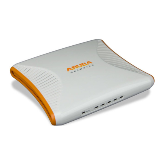
About the RAP-5
The Aruba RAP-5 is part of a comprehensive remote network solution. This
device works in conjunction with other Aruba products, such as Aruba Mobility
Controllers, and provides the following capabilities:
Can be deployed remotely as a Remote Access Point (RAP)
Protocol-independent networking functionality
Can be centrally managed, configured, and upgraded through an Aruba
Mobility Controller
Package Contents
1 x RAP-5 Remote Access Point
1 x Installation Guide (this document)
1 x RJ-45 Ethernet Cable
1 x Power Adapter (12V 1.25A)
Inform your supplier if there are any incorrect, missing or damaged parts. If possible,
retain the carton, including the original packing materials. Use them to repack the
product in case there is a need to return it.
Before You Begin
Before installing your RAP-5 Remote Wireless Access Point, please ensure you
have the following:
1 x RJ-45 Ethernet Cable
1 x Power Adapter
1 x RAP-5
RAP-5 Overview
Rear/Bottom View
Figure 1 Rear/Bottom View
Power
Socket
Power
100/1000Base-T
Gigabit
0
Ethernet Port
1
10/100Base-T
2
Gigabit
Ethernet Port
3
4
USB
Port
Reset
Reset
Button
10/100/1000Base-T Ethernet Port
The RAP-5 has one 10/100/1000Base-T port used for wired connectivity. This port
is labeled 0.
10/100Base-T Ethernet Ports
The RAP-5 has four 10/100Base-T (RJ-45) ethernet ports for wired network
connectivity. These are ports 1 through 4.
DC IN (Power Socket)
The device is turned on when the attached power adapter (included) is plugged
into a power source (outlet). The device turns off by unplugging the device from
the power source.
USB Port
The purpose of this USB port is to support Cellular modems.
Reset Button
To reset the RAP-5, insert a small, narrow object, such as a pin or paperclip, into
the hole indicated in
Figure 1
and press and hold the button while powering on
the RAP-5. This will return the device to factory default settings.
Front/Top View
Figure 2 Front/Top View
Power
4
3
2
1
0
LEDs
The RAP-5 has six LED status indicators.
POWER: Indicates whether or not the RAP-5 is powered on
Gigabit Ethernet Port 0: Indicates activity and/or status on this port
Fast Ethernet Ports 1-4: Indicates activity and/or status on these ports.
LED
Color
Activity Action
POWER
Green,
Off
No Power
Red
On
Power on, device connected
(Green)
Flashing
Device booting, not provisioned. LED will
(Green)
remain green for 1 second, then turn off for 1
second.
Flashing
Device is provisioning or in local
(Green)
troubleshooting mode. LED will remaining
green for 5 seconds, then turn off for 1
second.
On
Device is not booting.
(Red)
Port 0 (WAN)
Green,
Off
No link
Amber
On
Link established at 10/100 Mbps
(Amber)
On
Link established at 1000 Mbps
(Green)
Flashing
Ethernet link activity
Ports 1 - 4 (LAN) Green,
Off
No link
Amber
On
Link established at 10 Mbps
(Amber)
On
Link established at 100 Mbps
(Green)
Flashing
Ethernet link activity
If the POWER LED remains RED for more than 10 seconds, please attempt
to power cycle the device. If the LED remains RED, contact your IT
administrator.
N O T E
The Aruba AP Setup
Installation
The RAP-5 is equipped with four rubber feet to prevent sliding when placed on a
desk or other flat surface. Additionally, the rubber feet prevent possible damage
to the flat surface.
Connecting the Cables
You must connect the RAP-5 to a network device that has access to the Internet,
such as a router or modem.
1. Connect one end of the provided RJ-45 cable to port 0 on the RAP-5.
2. Connect the other end of the RJ-45 cable to a free RJ-45 port on your modem
or router.
3. Attach the provided power adapter to the DC IN port on the RAP-5.
4. Connect the other end of the power adapter to a power outlet.
The POWER LED is lit (solid green) when the RAP-5 is receiving power.
Verifying Successful Installation
Once the RAP-5's PWR LED has come up and the boot cycle is complete, you can
connect to your company or corporate network.
See the Provisioning at Home section if you are unable to connect
successfully.
N O T E
Provisioning at Home
If your IT administrator instructed you to provision your RAP-5, complete the
following steps after the RAP-5 has been powered.
1. Connect one end of a second RJ-45 cable to port 1 on the RAP-5 and the other
end to your computer.
2. Open a web browser and navigate to any URL.
3. An Aruba web page will appear (see
Figure
3), requesting the IP address of
the master controller. Enter the IP address provided to you by your IT
administrator.
The RAP-5 will connect to the designated master controller and download the
necessary provisioning information. When the RAP-5 comes back up, it is ready
to use.
Contact your IT administrator if you are still unable to connect successfully.
N O T E
Figure 3 Manual Provisioning Page
When the RAP-5 has been successfully provisioned, a screen
(Figure
This screen displays network information pertaining to the connection between
the RAP-5 and its controller.
Figure 4 Provisioning Successful
If your RAP-5 does not provision successfully, the screen indicates where the
failure occurred, as shown in
Figure
5. If this (or a similar) screen appears,
contact your IT administrator.
Figure 5 Unable to Complete Provisioning Process
Local Debugging
The RAP-5 includes built-in local debugging capabilities that allow you to report
information about the RAP-5 to your IT administrator. To access this tool, please
contact your IT administrator.
Troubleshooting
If your computer is to obtain an IP from the RAP-5, try the following trouble
shooting steps. If the procedure is not successful, contact your IT administrator.
1. Unplug the Power and Ethernet cables.
2. Reset the RAP-5 to its factory default setting by holding down the reset
button (use a pin or paperclip to hold down the button).
3. Power on the RAP-5 (plug-in the power cord) while still holding down the
reset button.
4. Wait for the power LED to start blinking (about 5 seconds) then release the
reset button.
5. Plug-in your WAN connection to port 0.
6. Connect your laptop to port 1 using the RJ-45 cable.
4) appears.
Advertisement

Related Manuals for Aruba Networks RAP-5


Summary of Contents for Aruba Networks RAP-5
- Page 1 Figure 1 Rear/Bottom View 1. Connect one end of a second RJ-45 cable to port 1 on the RAP-5 and the other 4. Wait for the power LED to start blinking (about 5 seconds) then release the end to your computer.
- Page 2 VPN client devices constitutes complete acceptance of liability by that individual or corporation for this action and indemnifies, in full, Aruba Networks, Inc. from any and all legal actions that might be taken against it with respect to infringement of copyright on behalf of those vendors.
Need help?
Do you have a question about the RAP-5 and is the answer not in the manual?
Questions and answers