Table of Contents
Advertisement
Quick Links
Advertisement
Table of Contents

Related Manuals for Aruba Networks MST200


Summary of Contents for Aruba Networks MST200
- Page 1 Aruba Networks MST200 Installation Guide...
- Page 2 3. Users shall purchase or use the company’s MST200 voluntarily. Users shall understand on their own initiative and abide voluntarily by policies, regulations or laws of their respective nation or local territories.
- Page 3 The company reserves fully the final interpretation of the MST200 and this manual. Safety Warnings The MST200 must be installed by trained professional installation technicians. All warnings below must be read and understood before installation. General Safety Warnings You can be killed or injured if performing antenna installation near electrical power lines.
- Page 4 The installation of the power switch must be performed by a trained professional technician. The power switch is not supplied with the MST200. The power cord must be assembled by a professional installer, and the final assembly must comply with related requirements.
- Page 5 RF Device Protection Before powering up the MST200, the RF port must be connected to an antenna or a valid load (not included in the standard accessories for MST200). Otherwise, the RF module may be burned out. Aruba will not take any responsibility for such damage. For RF module with power less than 100mW, in test environment, it is allowed worked without load but should be within 30 minutes.
- Page 6 (e.i.r.p.) is not more than that necessary for successful communication. Region Selection Limited by local law regulations, version for North America does not have region selection option. MST200 Installation Guide...
-
Page 7: Table Of Contents
................................7 NTERFACES INSTALLATION PREPARATIONS ..........................8 ..........................8 REPARING NSTALLATION OOLS ......................... 8 XAMINING THE NSTALLATION MST200 INSTALLATION .............................. 9 MST200 ..........................9 NSTALLING ON A POLE MST200 ............................. 14 ROUNDING THE ........................15 ONNECTING THE THERNET CABLE NOTE ....................................17... -
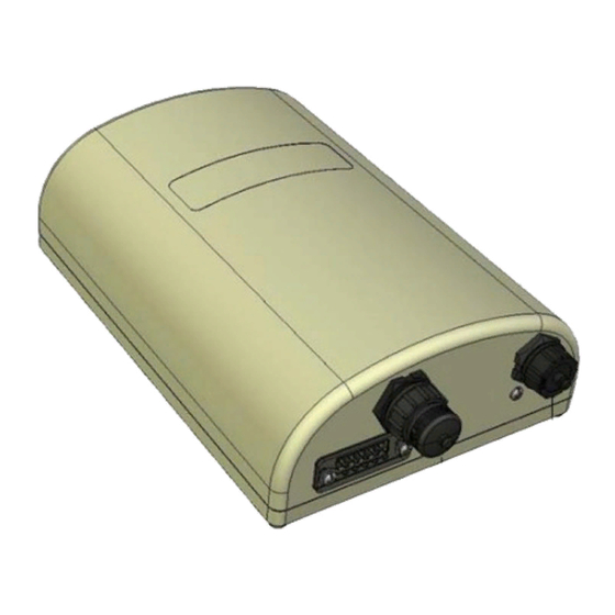
Page 8: Product Overview
1 Product Overview 1.1 Interfaces Figure 1-1 Interfaces on MST200 Ethernet interface (POE) USB console interface Grounding hole MST200 Installation Guide... -
Page 9: Installation Preparations
This chapter describes the preparations for MST200 installation, including preparation of installation tools,selection of installation sites and etc. 2.1 Preparing Installation Tools When installing MST200, you may need the following tools. You shall select the tools according to the actual situation. Table 2-1 Installation tools list... -
Page 10: Mst200 Installation
3.1 Installing MST200 on a pole The mounting assembly for installing MST200 concludes: a pair of pole anchors, a positioning bracket, a mounting bracket and bolts. MST200 can be mounted on a pole or wall. (Pole diameter must be 40 to 60 MST200 Installation Guide... - Page 11 MST200 will be mounted.) Note If using M8 x150 long bolts (not provided in the box shipped with MST200), the MST200 can be mounted on a pole with 96mm diameter. Figure 3-1 the mounting assembly...
- Page 12 Step 1 F asten the positioning bracket onto the back of the MST200 using the five M6 x 12 bolts (with flat and spring washers) . (There is screw thread in the screw hole of the mounting bracket, so nuts are...
- Page 13 M8 x 16 bolts (with flat washers and spring washers) to fasten the positioning Step 2 bracket flanges to the mounting bracket flanges. Figure 3-4 Positioning bracket and mounting bracket bolted at flanges MST200 Installation Guide...
- Page 14 Step 3 When mounting the MST200 to a pole, use the four M8 x 110 bolts (with flat washers, spring washers and nuts) and two pole anchors to fasten the mounting bracket to the pole.
-
Page 15: Grounding The Mst200
Figure 3-5 Mounting MST200 on a pole 3.2 Grounding the MST200 The grounding must be completed before powering up the MST200.The residence of grounding wire should be less than 5 ohm and the grounding cable’s cross-section area should be no less than 6 .The grounding hole is at the left side of the MST200. -
Page 16: Connecting The Ethernet Cable
Step 2 Fasten the copper lug to the grounding hole on the MST200 with the M4 x12 bolt and external-tooth washer. 3.3 Connecting the Ethernet cable Step 1 Remove the protective cap on the Ethernet interface. - Page 17 Note ① A waterproof Ethernet connector kit will be shipped with the MST200, including shielded RJ45 ② ③ ④ ⑤ connector, gasket mat, waterproof Ethernet connector socket, locknut, seal ring, ⑥ sealing nut, as shown in the figure below:...
-
Page 18: Note
4 Note To log onto the MST200 via Console port, use the setting as shown in table below: Baud Rate 115200 Data Bits Parity None Stop Bits Flow Control None Default Username and Password root : public MST200 Installation Guide...
Need help?
Do you have a question about the MST200 and is the answer not in the manual?
Questions and answers