Table of Contents
Advertisement
Sonance
DSP2-750 MKII Amplifier
SONAMP MULTI-CHANNEL POWER
Rear Panel 4/ 2/ 2018
Die Line Do N ot Print
AMPLIFIER WITH SonARC V2
Prints W hite
I N S T R U C T I O N M A N U A L
1-L
1-R
2-L
IN
OUT
Sonance
DSP2-750 MKII Amplifier
Rear Panel 4/ 2/ 2018
Die Line Do N ot Print
Prints W hite
1-L
1-R
2-L
IN
OUT
2-R
IN
DSP 2-750 MKII
OUT
1L
2-R
IN
OUT
1L
_
_
+
+
_
+
BRIDGE
4 Ω MIN
1R
DSP 2-750 MKII
_
_
+
+
_
+
BRIDGE
4 Ω MIN
1R
DSP 2-750 MKII
DSP 2-750 MKII
S/N
CAUTION
RISK OF ELECTRIC SHOCK
DO NOT OPEN
AVIS
RISQUE DE CHOC ELECTRIQUE
NE PAS OUVRIR
IR
IR
CONTROL
STATUS
T10AL/250VAC
IN
CAUTION
REPLACE FUSE ONLY WITH SAME
TYPE AND RATING OF FUSE
AC 100-120V ~ 60Hz
ATTENTION
REMPLACER UNIQUEMENT AVEC
AC 220-240V ~ 50Hz
LE MEME TYPE ET CALIBRE DU
VOLTAGE TRIGGER
FUSIBLE
IN
OUT
OUT
_ _
+
+
TCP/IP
DEFAULT IP
3-30 volts AC/DC
192.168.1.50
Advertisement
Table of Contents

Related Manuals for Sonance DSP 2-750 MKII


Summary of Contents for Sonance DSP 2-750 MKII
- Page 1 Die Line Do N ot Print AMPLIFIER WITH SonARC V2 Prints W hite I N S T R U C T I O N M A N U A L DSP 2-750 MKII CAUTION RISK OF ELECTRIC SHOCK DO NOT OPEN...
-
Page 2: Table Of Contents
TABLE OF CONTENTS Safety Introduction/Box Contents Front Panel/Rear Panel Amplifier Power Requirements Connections & Volume Level Controls Protection Circuitry & LEDs/Stacking Network Connection Instructions Basic Setup Advanced Setup Specifications Appendix A & B Troubleshooting Warranty... -
Page 3: Safety
WEEE directive, require special reuse and recycling processing. For this reason BE PLACED ON THE APPLIANCE. Sonance has arranged with our distributors in European Union member nations to collect and recycle this The lightning flash with arrowhead... -
Page 4: Introduction/Box Contents
Introduction Unpacking Thank you for purchasing the Sonance Sonamp DSP 2-750 MKII Save the carton and polystyrene inserts for future safe transport in amplifier. When properly installed, this amplifier will give you many case the amplifier is moved or requires shipping for repair. years of entertainment pleasure. To get the most out of your new Before proceeding with installation, locate the serial number on the... -
Page 5: Front Panel/Rear Panel
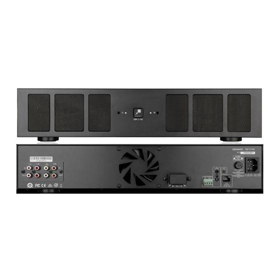
3-30 volts AC/DC 192.168.1.50 4 Ω MIN Figure 3: Sonamp DSP 2-750 MKII Multi-Channel Power Amplifier Rear Panel NOTE: L/R LINE IN/LOOP OUTPUT CARD CAN BE REPLACED WITH SONANCE DIGITAL INPUT MODULE (SKU 93099 SOLD SEPARATELY) FOR DSP 2-750 MKII ULTIMATE PERFORMANCE ENHANCEMENT THROUGH DIRECT CONNECTION TO A DIGITAL SOURCE. -
Page 6: Rear Panel
AC or DC. The Voltage Output supplies a 12 volt DC signal to solid white. This means amplifier has power and is turned ON and control additional amplifiers or other equipment. ready to operate. When the Sonance logo is slightly dimmed, the amplifier is in standby mode. When the Sonance logo blinks white, IR Control the amplifier power supply is in thermal protection. In this situation, IR control is established via the 3.5mm mono mini input jack on the... -
Page 7: Amplifier Power Requirements
Powering the Amplifier If the electrical service is subject to frequent sags, spikes or The Sonamp DSP 2-750 MKII features a removable IEC power brownouts, a power conditioner designed for use with high fidelity cord (see Figure 6). A 14 gauge EIA standard 120 volt grounded equipment should be employed to protect the amplifier. power cable is included with the amplifier. Each time the amplifier’s power cord is initially plugged in and the POWER switch is turned... -
Page 8: Connections & Volume Level Controls
Do N ot Print Speaker Connections Source Connections DSP 2-750 MKII Prints W hite For the best sound you should use On the left side of the rear panel are the audio inputs for the left premium speaker wire that complies and right channels. -
Page 9: Protection Circuitry & Leds/Stacking
Protection Circuitry and LEDs Rack Ear Installation DSP 2-750 MKII The Sonamp amplifiers have a multi-stage protection system to The DSP 2-750 MKII ships with two rack ears. Unscrew the four prevent damage to your amplifier and speakers. Phillips head screws (M4 x 0.7 pitch x 10mm long) found on each side of the left and right forward section of amplifier. Use these Amplifier Channel Protection DSP 2-750 MKII... -
Page 10: Network Connection Instructions
Connecting to Your SonARC Homepage 1. The amplifier’s factory default settings has DHCP set to ON. 2. Connect the amplifier to a network with a router. Make sure the computer and amplifier are on the same network. 3. Turn on the amplifier. 4. The amplifier will be issued an IP address by the router. 5. Use an IP scanner to determine the IP address of the Sonance DSP amplifier on the network. We recommend Fing app for IOS, Advanced IP Scanner for Windows devices and LanScan for macOS. 6. Network devices will show up and the amplifier will be named Sonance. 7. Open Safari or Chrome. -
Page 11: Advanced Setup
IP Setup the woofers. DHCP On/Off DHCP ON/OFF is the first option in IP SETUP. All Sonance DSP NOTE: LEFT AND RIGHT CHANNELS ARE LINKED. OUTPUT VOLUME IS series amplifiers ship with DHCP (Dynamic Host Connection LINKED TO TURN ON VOLUME IN BASIC SETUP. Protocol) ON. In most installations DHCP should be left ON except when you are using a control system for IP control. If you... -
Page 12: Sleep Mode
IP Subnet Mask Voltage The third setting in the IP SETUP section is the IP Subnet Mask. In the Voltage Auto On mode, the amplifier will power off This is an advanced network setup function. Under most immediately when the trigger voltage has been removed. When a circumstances this field should not need to be edited. 3-30V AC or DC voltage is sent to the amplifier, it will take 6-8 Making changes in this field should only be done by an experience seconds for the amplifier to reproduce audio after going through its network administrator. -
Page 13: Input Setup
Mono. DSP Preset NOTE: FRONT PANEL VOLUME CONTROLS OVERWRITE THIS SETTING. Apply any of the available Sonance DSP presets to each channel of the amplifier independently. You can apply any open preset & then Maximum Volume make modifications on the EQ settings page. IP or IR can be used to limit how loud the speakers will play in certain areas. - Page 14 1. Import speaker preset to a location on your computer. This can Test Signal be accomplished by saving a DSP preset downloaded from Sonance website. The SonARC software includes a built in pink noise generator. 2. Select the location you would like to store the new preset using The pink noise signal can be used in conjunction with a real time the SELECT PRESET TO EDIT pull down menu.
-
Page 15: Filter Type
Parametric EQ Crossover All Sonance DSP amplifier models feature a 10 band parametric LP Xover / HP Xover EQ. Adjustments made to the EQ will be displayed on the output This setting turns the high and low pass crossovers on and off. frequency response graph. We strongly suggest not adjusting the Frequency EQ without proper measurement equipment. In this field you can enter any frequency between 20Hz-20kHz. EQ On/Off Turns each of the 10 parametric EQ filters on and off. -
Page 16: Specifications
Specifications SONAMP DSP 2-750 MKII Number of Channels 2 (1 stereo pair) Power Output - 8 ohms (Stereo) 500 Watts RMS per channel (all channels driven) Power Output - 4 ohms (Stereo) 750 Watts RMS per channel (all channels driven) Power Output - 8 ohms (Bridged) - Page 17 Amplifier Factory Reset Steps Step 1 In a URL address window enter the amplifiers IP address with the extension /Update.htm (ex. 192.168.1.100/Update.htm) Step 2 On the update page, locate the red reset button. Use this button to completely reset the amplifier. Step 3 Return to the Home Page to set up the amplifier. Note: EQ presets will not be deleted. APPENDIX B DSP 2-750 MKII Amplifier - Auto On/Sleep Mode Details Auto On Setting Sleep Mode Options Time To Music Ethernet Audio Off Always on Always on Audio...
-
Page 18: Troubleshooting
Out of the Box Troubleshooting Cause: The SonARC bridging option is engaged but the speakers are No Power not wired properly for bridge mode. Front panel Power LED does not illuminate when AC cord is Solutions: plugged into an outlet and the amp is switched on. •... -
Page 19: Factory Reset
• Turn the amp ON. • Test playback to see if the speaker connected to the non- functioning channel works. For additional support, contact Dana Innovations Technical Support www.techsupport@sonance.com. • If the affected channel is now working, the problem could be with that channel at the source or with the interconnect cable for the non-functioning channel. -
Page 20: Warranty
(RMA), and must deliver the Product to Sonance shipping prepaid during the warranty period, together with the original sales receipt, or invoice or other satisfactory proof of purchase. ©2018 Sonance. All rights reserved. Sonance is a registered trademarks of Dana Innovations.
Need help?
Do you have a question about the DSP 2-750 MKII and is the answer not in the manual?
Questions and answers