Advertisement
Advertisement

Related Manuals for Sonance SR 2-125


Summary of Contents for Sonance SR 2-125
- Page 1 I N S T R U C T I O N M A N UA L SR 2-125 TWO-CHANNEL AMPLIFIER 33-7575 05.24.16...
-
Page 2: Table Of Contents
S R 2 - 1 2 5 T W O - C H A N N E L A M P L I F I E R I N S T R U C T I O N M A N U A L TABLE OF CONTENTS Safety Introduction/Box Contents... -
Page 3: Safety
You should always follow these basic safety precautions when using a marked change in performance. your SR 2-125 amplifier to reduce the risk of fire, electric shock, and injury to persons: • The amplifier has been dropped, or the enclosure damaged. - Page 4 S R 2 - 1 2 5 T W O - C H A N N E L A M P L I F I E R I N S T R U C T I O N M A N U A L I N S T R U C T I O N S I M P O R TA N T E S C O N C E R N A N T L A S É...
-
Page 5: Box Contents
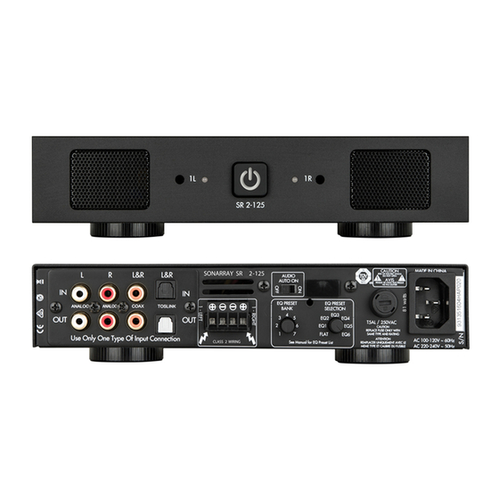
S R 2 - 1 2 5 T W O - C H A N N E L A M P L I F I E R I N S T R U C T I O N M A N U A L Introduction Unpacking Thank you for purchasing the SONARRAY SR 2-125 amplifier. Save the carton and polystyrene inserts for future safe transport in When properly installed, this amplifier will give you many years of case the amplifier is moved or requires shipping for repair. - Page 6 S R 2 - 1 2 5 T W O - C H A N N E L A M P L I F I E R I N S T R U C T I O N M A N U A L FIGURE 2: SR 2-125 TWO-CHANNEL AMPLIFIER FRONT PANEL SR 2-125 Front Panel 1.
-
Page 7: Front Panel/Rear Panel
Power Switch Inputs The power switch turns the amplifier on and off. The SR 2-125 amplifier has analog, coax and toslink LINE INPUTS and loop OUTPUTS. When the power switch is lit solid white, the amplifier has power, is turned ON and ready to operate. - Page 8 INTO A CONVENIENCE OUTLET ON ANY OTHER AUDIO OR VIDEO COMPONENT. If the electrical service is subject to frequent sags, spikes, or FIGURE 8: SR 2-125 LEFT, RIGHT LINE INPUTS brownouts, a power conditioner designed for use with high fidelity equipment should be employed to protect the amplifier.
-
Page 9: Speaker Connections
The source connected to the LEFT and RIGHT LINE IN Inputs pass through the LEFT and RIGHT LINE Outputs (see Figure 10). This also applies to the Coax and Toslink inputs. FIGURE 10: SR 2-125 LEFT, RIGHT LINE INPUTS/OUTPUTS... -
Page 10: Protection Circuitry And Leds
If a channel encounters a short-circuit or an extremely low impedance this will cause the affected channel outputs to automatically mute. The SR 2-125 amplifier ships with two long rack ears for when the The output of the affected channel will remain muted until the fault amplifier is to be used alone in a 1U space. -
Page 11: Quick Setup Page
NOTE: THE AUDIO AUTO ON - ON MODE USES THE LEAST AMOUNT OF AC POWER WHEN THE AMPLIFIER IS NOT OPERATING. FIGURE 17: SR 2-125 EQ PRESET BANK & EQ PRESET SELECTION FIGURE 15: SR 2-125 AUDIO AUTO ON - ON... -
Page 12: Specifications
8 5/8” x 2 1/8” x 16 13/16” (219mm x 54mm x 427mm) Dimensions w/ Rack Ears w/o Feet (W x H x D) 19” x 1 3/4” x 16 13/16” (482mm x 44mm x 427mm) Shipping Weight 11 lbs (5.0kg) CAD Files available for download at www.sonance.com/outdoor/sonarray... -
Page 13: Warranty
TO THE EXTENT PERMITTED BY LAW, THE WARRANTY SET FORTH ABOVE IS IN LIEU OF, AND EXCLUSIVE OF, ALL OTHER WARRANTIES, EXPRESS OR IMPLIED, AND IS THE SOLE AND EXCLUSIVE WARRANTY PROVIDED BY SONANCE. ALL OTHER EXPRESS AND IMPLIED WARRANTIES, INCLUDING THE IMPLIED WARRANTIES OF MERCHANTABILITY, IMPLIED WARRANTY OF FITNESS FOR USE, AND IMPLIED WARRANTY OF FITNESS FOR A PARTICULAR PURPOSE ARE SPECIFICALLY EXCLUDED.
Need help?
Do you have a question about the SR 2-125 and is the answer not in the manual?
Questions and answers