
Related Manuals for Sonance SONAMP 2-100


Summary of Contents for Sonance SONAMP 2-100
- Page 1 I N S T R U C T I O N M A N UA L ® SONAMP MULTI-CHANNEL POWER AMPLIFIERS 2-100 & 12-50...
-
Page 2: Important Safety Information
You should always follow these basic safety precautions when using a marked change in performance. your Sonamp 2-100 or Sonamp 12-50, to reduce the risk of fire, electric shock, and injury to persons: • The amplifier has been dropped, or the enclosure damaged. - Page 3 SONAMP 2-100 & 12-50 MULTI-CHANNEL POWER AMPLIFIER INSTRUCTION MANUAL I N S T R U C T I O N S I M P O R TA N T E S C O N C E R N A N T L A S É C U R I T É...
-
Page 4: Box Contents
SONAMP 2-100 & 12-50 MULTI-CHANNEL POWER AMPLIFIER INSTRUCTION MANUAL Introduction Box Contents Thank you for purchasing the Sonance Sonamp 2-100 or 12-50 Your Sonamp 2-100 box should contain: amplifier. When properly installed, this amplifier will give you (1) Instruction Manual many years of entertainment pleasure. -
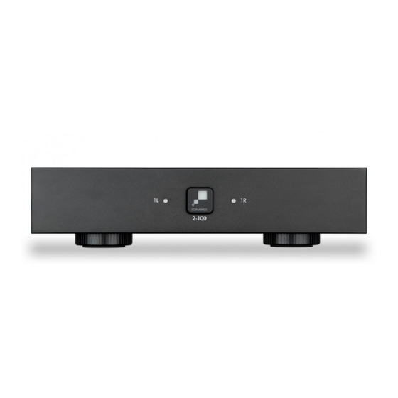
Page 5: Front Panel
SONAMP 2-100 & 12-50 MULTI-CHANNEL POWER AMPLIFIER INSTRUCTION MANUAL FIGURE 3: SONAMP 2-100 MULTI-CHANNEL AMPLIFIER 2-100 CAUTION 2-100 LEVEL LEVEL RISK OF ELECTRIC SHOCK BRIDGE DO NOT OPEN AVIS RISQUE DE CHOC ELECTRIQUE NE PAS OUVRIR VOLTAGE TRIGGER AUTO ON... - Page 6 The Sonamp amplifiers feature removable IEC power connectors. Plug the female end of the power cord into the Power Cord When the Sonance logo on the power switch is lit solid white, the Connector on the amplifier rear panel and plug the male end into a amplifier has power and is turned ON and ready to operate.
-
Page 7: Powering The Amplifier
220-240V AC Full Power All Channels @8 ohms Full Power All Channels @4 ohms 1/8 Power All Channels @8 ohms 1/8 Power All Channels @4 ohms @ Idle @ Standby 0.45 FIGURE 8: SONAMP 2-100 & 12-50 MULTI-CHANNEL AMPLIFIER POWER REQUIREMENTS... -
Page 8: Source Connections
1-LEFT 1-RIGHT SONAMP 2-100 & 12-50 MULTI-CHANNEL POWER AMPLIFIER INSTRUCTION MANUAL Source Connections 2-100 Bridging Channels 2-100 & 12-50 STEREO MONO STER STEREO MONO IMPORTANT: THE MINIMUM SPEAKER IMPEDANCE FOR BUSS INPUT A BUSS INPUT B On the left side of the 2-100 rear panel are the audio inputs for the SS INPUT B BRIDGED OPERATION IS 8 OHMS. -
Page 9: Protection Circuitry And Leds
1U space. Unscrew the four Phillips head screws To place two Sonamp 2-100 or DSP 2-150 in a single rack unit (M4 x 0.7 pitch x 10mm long) found on each side of the left and order RACK MOUNT BRACKET FOR SONAMP 2-100 &... -
Page 10: Specifications
SONAMP 2-100 & 12-50 MULTI-CHANNEL POWER AMPLIFIER INSTRUCTION MANUAL SPECIFICATIONS SONAMP 2-100 Number of Channels 2 (1 stereo pair) Power Output - 8 ohms (Stereo) 100 Watts RMS per channel (all channels driven) Power Output - 4 ohms (Stereo) 156 Watts RMS per channel (all channels driven) - Page 11 SONAMP 2-100 & 12-50 MULTI-CHANNEL POWER AMPLIFIER INSTRUCTION MANUAL SPECIFICATIONS SONAMP 12-50 Number of Channels 12 (6 stereo pairs) Power Output - 8 ohms (Stereo) 50 Watts RMS per channel (all channels driven) Power Output - 4 ohms (Stereo) 50 Watts RMS per channel (all channels driven)
- Page 12 SPECIFICALLY EXCLUDED. No one is authorized to make or modify any warranties on behalf of Sonance. The warranty stated above is the sole and exclusive remedy and Sonance’s performance shall constitute full and final satisfaction of all obligations, liabilities and claims with respect to the Product.
Need help?
Do you have a question about the SONAMP 2-100 and is the answer not in the manual?
Questions and answers