Table of Contents
Advertisement
Quick Links
Download this manual
See also:
Instruction Manual
Advertisement
Table of Contents

Related Manuals for Hioki 3274


Summary of Contents for Hioki 3274
- Page 1 3274 3275 Instruction Manual CLAMP ON PROBE 99 Washington Street Melrose, MA 02176 Phone 781-665-1400 Toll Free 1-800-517-8431 Visit us at www.TestEquipmentDepot.com May 2015 Revised edition 5 3275A981-05 15-05H...
-
Page 2: Table Of Contents
Contents Introduction Inspection Notes on Safety Notes on Use Chapter 1 Overview 1.1 Product Overview 1.2 Features 1.3 Names of Parts 1.4 Parts of the Sensor Chapter 2 Specifications 2.1 Product Specifications 2.2 Standards Applying Chapter 3 Measurement Procedure 3.1 Notes on Use 3.2 Preparations for Measurement 3.3 Demagnetizing and Zero Adjustment 3.4 Measurement Procedure... -
Page 3: Introduction
___________________________________________________________________ Introduction Thank you for purchasing this HIOKI 3274, 3275 CLAMP ON PROBE. To obtain maximum performance from the device, please read this manual first, and keep it handy for future reference. Inspection When you receive the device, inspect it carefully to ensure that no damage occurred during shipping. -
Page 4: Safety Symbols
___________________________________________________________________ Safety Symbols This manual contains information and warnings essential for safe operation of the device and for maintaining it in safe operating condition. Before using the device, be sure to carefully read the following safety notes. symbol printed on the device indicates that the user should refer to a corresponding topic in the manual (marked with the symbol) before using the relevant... -
Page 5: Notes On Use
___________________________________________________________________ Notes on Use Follow these precautions to ensure safe operation and to obtain the full benefits of the various functions. Do not measure around a bare conductor. Doing so DANGER may result in short-circuit or electric shock. Take measurements at a location on an insulated wire where there is sufficient insulation for the circuit voltage. - Page 6 ___________________________________________________________________ Before clamping the conductor being measured, DANGER make sure that the insulation on the conductor is undamaged. Also, take care not to damage the insulation when clamping the conductor. Any damage to the insulation could cause an electric shock. ...
- Page 7 ___________________________________________________________________ When using a measurement instrument that does DANGER not provide isolation between its input terminals and chassis or other input terminals, please pay attention to the following points. If a signal is applied to an input terminal other than that to which this device is connected, do not connect the ground-side terminal to any non- ground potential.
- Page 8 If you find any damage, contact your dealer or Hioki representative. This device is not designed to be entirely water- or dust- proof. To avoid damage, do not use it in a wet or dusty environment.
- Page 9 ___________________________________________________________________ The matching surfaces of the sensor head are CAUTION precision ground, and should be treated with care. If these surfaces are scratched, performance may be impaired. Do not apply a static electricity or other source of high voltage to the sensor.
- Page 10 Include cushioning material so the device cannot move within the package. Be sure to include details of the problem. Hioki cannot be responsible for damage that occurs during shipment. Use the original packing materials when transporting the device, if possible.
-
Page 11: Chapter 1 Overview
Model 3274 : DC to 10 MHz Model 3275 : DC to 2 MHz Large diameter allows high-current measurements. Easy protection function to avoid self-heating during excessive input. Unique HIOKI development of thin film Hall effect element ___________________________________________________________________ Chapter 1 Overview... -
Page 12: Names Of Parts
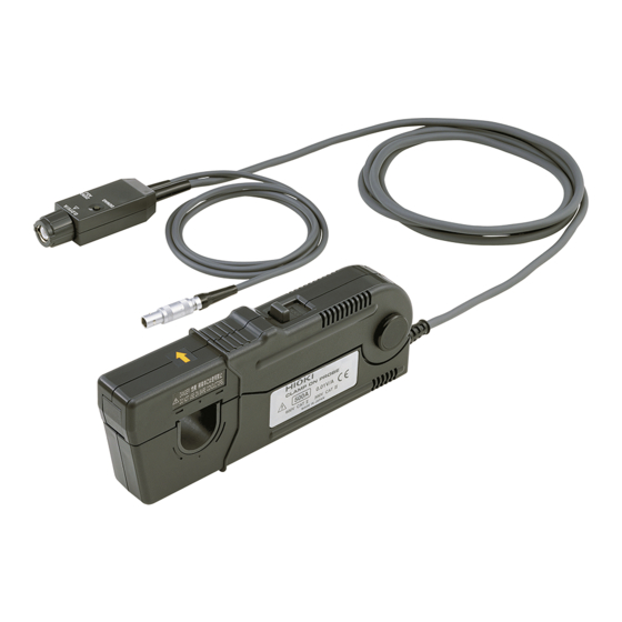
___________________________________________________________________ 1.3 Names of Parts External view Current direction indication "LOCK" indication Terminator Sensor Power supply cable (inside) Sensor cable "UNLOCK" indication ___________________________________________________________________ Chapter 1 Overview... -
Page 13: Parts Of The Sensor
___________________________________________________________________ 1.4 Parts of the Sensor 1. Clamp This clamps around the conductor to be measured. 2. Slider This slider opens the clamp. Always use it to open and close the clamp. 3. Lever This lock mechanism keeps the clamp closed. 4. - Page 14 The output of this device is terminated internally. NOTE Since the output resistance is approx. 7 Ω (model 3274) and approx. 40 Ω (model 3275), the device must be used with a high-impedance input to the measuring instrument. With an input impedance of 50 Ω, accurate measurement is not possible.
-
Page 15: Chapter 2 Specifications
±3 (73 ±5.4 ) after the power has Guaranteed at 23 been on for 30 minutes. Model 3274 : DC to 10 MHz (-3 dB) Bandwidth (Typical characteristics shown in Fig.1) Model 3275 : DC to 2 MHz (-3 dB) (Typical characteristics shown in Fig.2) - Page 16 Temperature 2% or less coefficient for Model 3274 (Input: 55 Hz 150 A, within a range of 0 sensitivity to 40 , within a range of 32 to 104 ) Model 3275 (Input: 50 Hz 500 A, within a range of 0...
-
Page 17: Standards Applying
___________________________________________________________________ 2.2 Standards Applying Safety EN61010 EN61326 ___________________________________________________________________ Chapter 2 Specifications... - Page 18 ___________________________________________________________________ Fig.1 Frequency characteristics (Typical) (3274) Fig.2 Frequency characteristics (Typical) (3275) Fig.3 Derating according to frequency(3274) ___________________________________________________________________ Chapter 2 Specifications...
- Page 19 ___________________________________________________________________ Fig.4 Derating according to frequency(3275) Fig.5 Input impedance (Typical) (3274) Fig.6 Input impedance (Typical) (3275) ___________________________________________________________________ Chapter 2 Specifications...
- Page 20 ___________________________________________________________________ ___________________________________________________________________ Chapter 2 Specifications...
-
Page 21: Chapter 3 Measurement Procedure
___________________________________________________________________ Chapter 3 Measurement Procedure 3.1 Notes on Use Before using the instrument, make sure to refer to〝Notes on Use 〟(p.3 to p.8). ___________________________________________________________________ Chapter 3 Measurement Procedure... -
Page 22: Preparations For Measurement
(2) Turn the power switch off and connect the power cord. (3) Connect the power plug of the 3274 or 3275 to the power receptacle of the 3269 or 3272. (4) Turn the 3269 or 3272 power switch on, and check that the front panel power indicator lights. -
Page 23: Demagnetizing And Zero Adjustment
(2) Set the input coupling of the waveform measurement instrument to DC. (3) Connect the output connector of the 3274 or 3275 to the input connector of the waveform measurement instrument. Turn the collar until it clicks, and check that it is locked securely. -
Page 24: Measurement Procedure
(5) It is now possible to monitor the current waveform. The output rate of the 3274 or 3275 is 0.01 V/A. The current sensitivity can be derived from the voltage sensitivity of the waveform measurement instrument. For example, if the voltage sensitivity is 10 mV/division, the current sensitivity is 1 A/division. - Page 25 3272. See Figure 1. Fig.7 Current consumption* vs. current to be measured (typical)(3274) *The sum total of a positive and negative current consumption Current consumption* vs. current to be measured (typical)(3275)
- Page 26 ___________________________________________________________________ The maximum continuous input range is based on CAUTION heat that is internally generated during measurement. Never input current in excess of this level. Exceeding the rated level may result in damage to the probe. The device may sustain damage from self-heating even at current levels that are lower than the maximum current value defined by the maximum rated current.
- Page 27 addition to the maximum rated current. The maximum peak current specifications are as follows: For Model 3274 300 A peak (discontinuous) ………. (1) 500 A peak (with a pulse width of 30 μs or shorter) ………. (2) For Model 3275 700 A peak (discontinuous) ……….
- Page 28 The output of this device is terminated internally. Since the output NOTE resistance is approx.7 Ω (3274) or approx.40 Ω (3275), the must be used with a waveform measurement instrument that has an input impedance of at least. Use a waveform measurement instrument with an input impedance of at least 1 MΩ.
- Page 29 ___________________________________________________________________ Pressing the demagnetizing switch (DEMAG) will cause a demagnetized waveform to be output from the instrument. Although it may be asymmetry with respect to the zero-volt line, the instrument has no malfunction. The reading may be affected by the position within the clamp aperture of the conductor being measured.
- Page 30 ___________________________________________________________________ Test Equipment Depot - 800.517.8431 - 99 Washington Street Melrose, MA 02176 TestEquipmentDepot.com ___________________________________________________________________ Chapter 3 Measurement Procedure...
Need help?
Do you have a question about the 3274 and is the answer not in the manual?
Questions and answers