Table of Contents
Advertisement
Advertisement
Table of Contents
Troubleshooting

Related Manuals for Charder MS-6121R


Summary of Contents for Charder MS-6121R
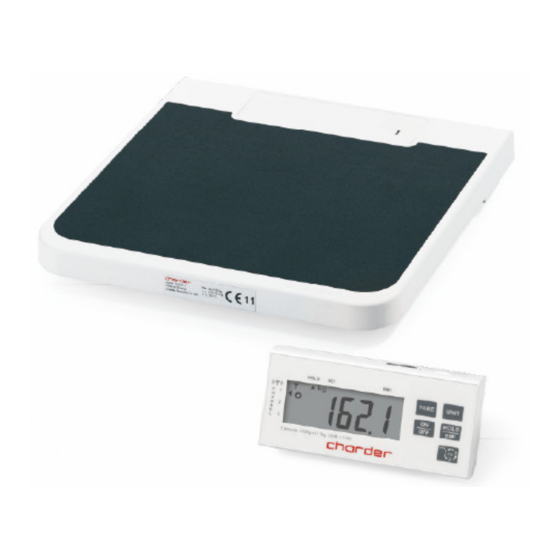
- Page 1 MS-6121R SERVICE MANUAL...
-
Page 2: Table Of Contents
TABLE OF CONTENTS PRECAUTIONS ............................2 GENERAL INFORMATION ........................2 GENERAL INSPECTION.......................... 2 TROUBLESHOOTING ..........................2 SPECIFICATION............................. 3 OVERLAY / PANEL ..........................3 KEY DESCRIPTION ..........................4 ERROR MESSAGE ..........................4 LCD FORMAT ............................5 WIRING..............................6 LOAD CELL............................8 CALIBRATION &... -
Page 3: Precautions
PRECAUTIONS READ the service manual BEFORE operating or servicing this equipment. FOLLOW the instructions carefully. Keep this manual for future reference. Don’t allow untrained personnel to operate, clean, inspect, maintain, service or tamper with this equipment. ALWAYS DISCONNECT this equipment from the power source before cleaning or performing maintenance. -
Page 4: Specification
SPECIFICATION MS 6121R MODEL# Capacity 250kg x 0.1kg 550lb x 0.2lb Division Accuracy ±200g ±0.4lb Units of Measure kg; lb ON/OFF, UNIT, TARE, HOLD/BMI, Function keys Channel switch Stabilisation time 1-2 seconds Operating temp. 5°C - 35°C DISPLAY: four 1.5V AA size batteries & Adaptor Power supply PLATFORM: four 1.5V AA size batteries &... -
Page 5: Key Description
KEY DESCRIPTION : To power ON and OFF the scale. : Press to tare weight. : Press this key to lock the weight value before or while weighing. To disable the weight lock (Hold) function, press HOLD key again or pick up the weight (Tare weight also) from the platform; display will come to zero weighing : Press to change measuring unit between kg and lb. -
Page 6: Lcd Format
LCD FORMAT ACTION: Problem- The scale shows non-complete segments when power on. Solution: • Turn off the scale and take out the batteries from the scale. • Check LCD pin. (Please refer to above LCD FORMAT) For instance, if the top left arrow (S1) disappears, then check pin 1 and pin 20. •... -
Page 7: Wiring
WIRING ACTION: 1. Remove battery from the scale. 2. Un-screw the lower housing. 3. Remove upper housing. 4. Make sure that all wire connectors are well and that no insulation material is touching the soldering contacts. 5. Make sure that all wires are connected to the correct points. Wiring Connector RED (solder pad “E+”) - Page 8 Junction Board CH-0810 (Deck) CN1: AC Jack Connector Load cell Connector Battery Connector Load cell Connector Load cell White wire Red wire Black wire sensor 1 sensor 2 sensor 3 sensor 4...
-
Page 9: Load Cell
LOAD CELL Check load cell for proper bridge resistances as below. MODEL MEASURING POINTS RESISTANCE E+ (RED) to E- (BLACK) 700 ± 15 ohms AL-1380 S+ (GREEN) to S- (WHITE) 700 ± 15 ohms ACTION: 1. Remove power (adaptor pin) from the system, check load cell for proper resistances. 2. -
Page 10: Calibration & Setting Origin Gravity Procedure
CALIBRATION & SETTING ORIGIN GRAVITY PROCEDURE In weighing mode long press UNIT key 6 sec until “CAL” followed by the weight value of the required calibration weight in display. “LoAd” is displayed alternatively. Carefully place the required adjustment weight (200kg or 500lb) in the centre of the weighing plate. -
Page 11: Service Menu Configuration Of Ms 6121R
SERVICE MENU CONFIGURATION OF MS 6121R... -
Page 12: Company Settings
COMPANY SETTINGS The setting of MS6121R must be set to following default settings: Function Description Default (Units): Kg/ Lb/ lb:oz kg, lb (Graduations): 1500d/2000d/2500d/3000d/6000d 2500d (Auto off time) 120/180/240/300/off seconds (Hold Range): 2d/5d/10d/15d (Gravity) on/off (Tare-IR): on/off... -
Page 13: Trouble Shooting
TROUBLE SHOOTING... -
Page 14: Schematics-Main Board
SCHEMATICS—MAIN BOARD Main Board (Indicator) CH-0838... - Page 15 Junction Board (Deck) CH-0810...
-
Page 16: Layout
LAYOUT PRIMARY AND SECONDARY SIDE OF MAIN BOARD CH-0838 EEprom PRIMARY AND SECONDARY SIDE OF JUNCTION BOARD (Deck) CH-0810... -
Page 17: Ms 6121R Parts & Assembly
MS 6121R PARTS & ASSEMBLY... -
Page 18: Ms 6121R Spare Part List
MS 6121R SPARE PART LIST CED P/N DESCRIPTION DRAWING NO. CE010001000017 CE010001000017 CE010001000017 CE010001000017 Indicator (DP4100 RF) DP4000 CE010002000034 CE010002000034 CE010002000034 CE010002000034 Base MS6121R 060014000918 060014000918 Overlay for base NP-5801 060014000918 060014000918 060014000921 060014000921 060014000921 060014000921 Overlay for indicator NP-5711 020018000076 020018000076 ADAPTOR (USA Type) -
Page 19: Instruction For Replacing Battery
INSTRUCTION FOR REPLACING BATTERY INSTALLING BATTERY IN THE PLATFORM. You can also use the adaptor as power supply. Installing 4 AA 1.5V batteries INSTALLING BATTERY IN THE DISPLAY Remove battery compartment cover Place new 4 * AA 1.5V batteries into the battery compartment. -
Page 20: Index
INDEX 1. List of Tables. • Specification. • Error Message. • Wiring. • Load Cell Resistance. • Calibration Procedure. • Approval Scale Company Settings. 2. List of Pictures. • Overlay/Panel. • LCD Format. • Load Cell. • Service Menu Configuration. •...
Need help?
Do you have a question about the MS-6121R and is the answer not in the manual?
Questions and answers