Table of Contents
Advertisement
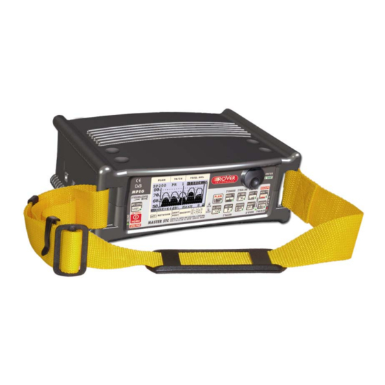
MASTER STC
ULTRA-PORTABLE ALL-IN-ONE ANALYZER
USER MANUAL
FM Radio
Analogue and digital terrestrial TV/CATV
4 – 1.010 MHz COFDM & QAM with demodulator
Analogue and Digital SAT
930 - 2250 MHz QPSK & 8PSK with demodulator
ROVER LABORATORIES S.p.A.
Via Parini 2 – 25019 Sirmione (BS) – ITALY
www.roverinstruments.com
Advertisement
Table of Contents

Related Manuals for Rover Instruments MASTER STC


Summary of Contents for Rover Instruments MASTER STC
- Page 1 MASTER STC ULTRA-PORTABLE ALL-IN-ONE ANALYZER USER MANUAL FM Radio Analogue and digital terrestrial TV/CATV 4 – 1.010 MHz COFDM & QAM with demodulator Analogue and Digital SAT 930 - 2250 MHz QPSK & 8PSK with demodulator ROVER LABORATORIES S.p.A. Via Parini 2 – 25019 Sirmione (BS) – ITALY...
- Page 2 MASTER STC USER MANUAL UG-MASTERSTC-1.06-BS1.0-EN-1.00 MANUAL CODE RELEASE DATE 21/05/2008 Changes possible. We all wish to sincerely thank you for choosing our measurement instrument, which is currently approved and everyday used by the major Service Providers, Broadcasters and by really many users all over in the world.
-
Page 3: Table Of Contents
MASTER STC USER MANUAL INDEX OVERVIEW..................... 8 FRONT PANEL & KEYBOARD DESCRIPTION .................. 8 SIDE BODYPANELS..........................9 RIGHTSIDE BODYPANEL ......................9 LEFTSIDE BODYPANEL......................9 SPEEDY MEASUREMENTS ?..............10 ONE TOUCH AND GO........................10 ANALOGUE TV, DIGITAL (COFDM) TV AND QAM (CATV) SIGNALS ........10 ANALOGUE SATELLITE SIGNALS, DIGITAL QPSK &... - Page 4 MASTER STC USER MANUAL DIRECT FREQUENCY INPUT ......................21 WHO IS THERE?AUTODISCOVERY ®....................22 FM /FM RADIO SIGNALS TUNING [87,5 – 108 MHz] ............. 23 10.3 EXPLORE USER DEFINED CHANNEL................... 24 PERFORMING MEASURES: MEAS....................25 11.1 THE SELECTED CHANNEL CARRIERS ON AN ANALOGUE TV SIGNAL ......25 VIDEO SIGNAL PEAK LEVEL MEASUREMENT ..............
- Page 5 MASTER STC USER MANUAL CABLE SYSTEM MEASUREMENTS....................42 14.1 INGRESS MODE (MEASUREMENTS ON THE FREQUENCY RANGE 4 ÷ 66 MHz) .... 42 MOVING THE MARKER (FREQUENCY VALUE)..............42 EDITING THE SWEEP TIME ....................43 EDITING THE END-OF-SCALE VALUE .................. 43 SETTING THE START FREQUENCY AND THE STOP FREQUENCY IN INGRESS MODE 43 SETTING THE START FREQUENCY....................
- Page 6 MASTER STC USER MANUAL 17.3 POINTING AND MOVING A MOTORIZED DISH (DiSEqC MOTOR)........54 SPECTRUM VIEW?........................55 MOVE ............................55 GOTO ............................55 STORE............................55 RESET ............................55 17.4 ANTENNA POINTING AID: BUZZER..................55 METER CONFIGURATION : PLAN ....................56 18.1...
- Page 7 MASTER STC USER MANUAL DELETING A LOGGER FILE (LOGGER MEMORY PLAN)............. 70 TECHNICAL SPECIFICATIONS ..............72 SERVICE NOTES AND GUARANTEE REGULATIONS (CEE AND EXTRA CEE) ......................74 FAULT IDENTIFICATION FORM ..............76 MANTAINING THE METER ................. 77 DISPOSAL OF ELECTRONIC EQUIPMENT ..........78...
-
Page 8: Overview
MASTER STC USER MANUAL OVERVIEW FRONT PANEL & KEYBOARD DESCRIPTION SECONDARY FUNCTION Bloc MAIN FUNCTION (press and hold for 2s) Main switch (ON/OFF) Level/Ch. Power meas. (press once) RESET (press and hold for 10”) MPEG SERVICE LIST Setup menu configuration key... -
Page 9: Side Bodypanels
MASTER STC USER MANUAL SIDE BODYPANELS RIGHTSIDE BODYPANEL LEFTSIDE BODYPANEL External power supply USB socket RF connector, type “F”, 75 ohm... -
Page 10: Speedy Measurements
USER MANUAL SPEEDY MEASUREMENTS ? The MASTER STC is a really complete instrument: you will be able to perform a wide variety of measurements on an extensive range of frequencies and of signal kinds. This user manual will guide you throughout all the functionalities of your meter. -
Page 11: Fm / Fm Radio Signals [87,5 - 108 Mhz]
MASTER STC USER MANUAL FM / FM RADIO SIGNALS [87,5 – 108 MHz] Connect the signal cable to the F-type connector [U] on the meter. Press once and release the PLAN [1] key. Highlight the item MANUAL MEMORY and select one of the MANU Memory Plans. -
Page 12: User Manual
MASTER STC USER MANUAL USER MANUAL TURN THE METER ON Press and release the HOME [A] key. TURN THE METER OFF Press and hold for 2’’ the HOME [A] key. CHECK THE BATTERY CHARGE STATUS When the meter is on, at the bottom left corner of the LCD display [C] an icon will show the current power source of the meter: built-in battery or mains external feed. -
Page 13: The Encoder - Standard Navigation Mode
MASTER STC USER MANUAL THE ENCODER – STANDARD NAVIGATION MODE Navigate into the various functions and menus of the MASTER STC is quick and easy. A multi-function continuous encoder [D] allows the user to surf all the meter functions, easily selecting the required function and quickly setting the desired values, by simply rotating and pressing the encoder itself. -
Page 14: Meter Configuration
MASTER STC USER MANUAL METER CONFIGURATION Press and hold for 2s the MPEG SERVICE LIST [B] key. METER LOUDSPEAKER VOLUME SETUP Using the Standard Navigation Mode, highlight the item VOLUME and adjust the volume level of the built-in loudspeaker: you can highlight one level among: 0% (loudspeaker off), 20%, 40%, 60%, 80%, 100% (max. -
Page 15: Field And Channel Power Measurement Unit
MASTER STC USER MANUAL FIELD AND CHANNEL POWER MEASUREMENT UNIT Using the Standard Navigation Mode, highlight the item UNIT and select the requested measurement unit: dBm, dBmV (dBmillivolt) dBuV (dBmicrovolt) LANGUAGE Using the Standard Navigation Mode, highlight the item LANGUAGE and select the required language. -
Page 16: Rf Input Signal Type (Cable Or Off Air)
MASTER STC USER MANUAL RF INPUT SIGNAL TYPE (CABLE OR OFF AIR) Using the Standard Navigation Mode, highlight the AUTOMEMORY item select the RF band, terrestrial analogue and digital, (TV ONLY) or cable (CATV). SATELLITE RECEPTION SETUP Rotate the encoder [D] to highlight the item SAT CONFIG, then press it to enter the selection menu. -
Page 17: Satscr User
MASTER STC USER MANUAL SatSCR USER: Using the Standard Navigation Mode, highlight the item SatSCR USER. and select the appropriate user. Up to 8 different users can be set up together with their relevant SCR frequency value. To manually enter each frequency value, proceed as described at paragraph SatSCR FREQ at page 17. -
Page 18: Manual Signal Standard Selection
MASTER STC USER MANUAL any frequency band by simply surfing the selected frequency band or by simply adjusting the frequency value to be tuned; from time to time and with no action by the user required the meter will detect the proper standard for the received signal, and will set the meter accordingly to it, together with the appropriate measurements set. -
Page 19: Dc At Rf In
MASTER STC USER MANUAL DC AT RF IN Press and hold for 2’’ the [0] key to activate the DC AT RF IN function When the DC power at RF in is on, the yellow led DC at RF IN [E] will be on. -
Page 20: Tv Signals - Audio Fm - Fm Radio Signals Analyzer
MASTER STC USER MANUAL TV SIGNALS – AUDIO FM – FM RADIO SIGNALS ANALYZER 10 SIGNAL TUNING: PLAN Connect the signal cable to the F-type connector [U] on the meter. Press once and release the PLAN [1] key. 10.1 NAVIGATE INTO THE SELECTED COUNTRY CHANNEL PLAN Using the Standard Navigation Mode, highlight the item TELEVISION. -
Page 21: Fine-Tuning The Frequency Value
MASTER STC USER MANUAL Using the Standard Navigation Mode, highlight the item MANUAL MEMORY, then select the required channels group (MANUxx plan). Press once and release the MEAS [5] key. The LCD [C] top row will display (from left to right): the selected channel plan, the currently tuned channel and the corresponding frequency value. -
Page 22: Who Is There?Autodiscovery
MASTER STC USER MANUAL 839,25 MHz), press the SAT FINDER [3] key. Once entered the desired frequency value, press the encoder knob[D] to confirm the selection. in case the frequency value is not applicable or invalid in the TV service range (e.g. -
Page 23: Fm /Fm Radio Signals Tuning [87,5 - 108 Mhz]
MASTER STC USER MANUAL FM /FM RADIO SIGNALS TUNING [87,5 – 108 MHz] When in the main Audio peak level measurement screen, using the Standard navigation Mode, highlight the tuned signal type (TV ANALOG / TV COFDM DVB-T/H). Using the encoder [D], select the item FM RADIO. -
Page 24: Explore User Defined Channel
MASTER STC USER MANUAL 10.3 EXPLORE USER DEFINED CHANNEL To create a channel plan (user defined list of channels), proceed as described in Chapter 15 CREATE MEMORY PLANS at page 46. Using the Standard navigation Mode, highlight the AUTOtv MEMORY item, and press the encoder knob [D] once. -
Page 25: Performing Measures: Meas
USER MANUAL 11 PERFORMING MEASURES: MEAS The MASTER STC is equipped with one LCD [C] display; at the same time, all the measurement values can be displayed on a high brightness screen and their reading is immediate and intuitive, also under direct sunlight and in any weather condition. -
Page 26: Video Vs. Audio Peak Level Ratio And Signal To Noise Ratio
MASTER STC USER MANUAL VIDEO Vs. AUDIO PEAK LEVEL RATIO AND SIGNAL TO NOISE RATIO From the previous measurement screen, press once and release the MEAS [5] key. The Video Vs. Audio peak level ratio and the signal to noise ratio will be displayed. -
Page 27: The Selected Channel Carriers On A Dtt (Cofdm) Signal
MASTER STC USER MANUAL 11.2 THE SELECTED CHANNEL CARRIERS ON A DTT (COFDM) SIGNAL THE CHANNEL IS SUCCESSFULLY LOCKED (THE LOCK ON THE LCD BOTTOM-RIGHT CORNER IS CLOSED) NOISE MARGIN, QUALITY TEST, MER AND ERROR COUNT MEASUREMENTS The second row of the LCD [C] displays TV COFDM DVB-T&H. -
Page 28: Constellation Chart And Ofdm Parameter
MASTER STC USER MANUAL These measurements are also displayed on a level bar with peak level memory. CONSTELLATION CHART AND OFDM PARAMETER From the previous measurement screen, press once and release the MEAS [5] key. The constellation will be displayed together with the following parameters: •... -
Page 29: Impulse Response Of The Selected Channel
MASTER STC USER MANUAL IMPULSE RESPONSE OF THE SELECTED CHANNEL From the previous measurement screen, press once and release the MEAS [5] key. The impulse response of the tuned channel will be displayed. The meter assumes as main signal (i.e. the signal with zero delay) the “echo” with the highest level among all the detected signals. -
Page 30: Channel Power Measurement
MASTER STC USER MANUAL In case the tuned bouquet contains the relevant information, the LCD will display: • the network name (NETW. NAME) • the bouquet name (BOUQ. NAME) • the current date (DATE), as stated in the bouquet itself •... -
Page 31: Displaying The Service List Of The Current Bouquet
MASTER STC USER MANUAL Press once and release the HOME [A] key to directly switch to the channel power measurement. DISPLAYING THE SERVICE LIST OF THE CURRENT BOUQUET Press once and release the MPEG SERVICE LIST [B] key once. The LCD [C] will display: •... -
Page 32: Spectrum Analyzer Mode
MASTER STC USER MANUAL WARNING: the buzzer function is active only with digital signals. It cannot be activated for analogue signals SPECTRUM ANALYZER MODE Proceed as described in Chapter 12 SPECTRUM ANALYZER MODEat page 38. THE CHANNEL IS NOT SUCCESSFULLY LOCKED (THE LOCK ON THE LCD... -
Page 33: The Selected Channel Carries On A Qam (Catv) Signal
MASTER STC USER MANUAL 11.3 THE SELECTED CHANNEL CARRIES ON A QAM (CATV) SIGNAL THE CHANNEL IS SUCCESSFULLY LOCKED (THE LOCK ON THE LCD BOTTOM-RIGHT CORNER IS CLOSED) The Autodiscovery will automatically detect the QAM signal type. The second row of the LCD [C] displays TV QAM, together with the relevant standard (e.g.: DVB-C). -
Page 34: Constellation Chart And Qam Parameter
MASTER STC USER MANUAL From the previous measurement screen, press once and release the MEAS [5] key once. The BER before Viterbi error correction (in this meter labeled as bBER or preBER) and the BER after Viterbi error correction (in this meter labeled as aBER or posBER) parameters will be displayed. -
Page 35: Bouquet Data Id
MASTER STC USER MANUAL BOUQUET DATA ID From the previous measurement screen, press once and release the MEAS [5] key. In case the tuned bouquet contains the relevant information, the LCD will display: • the network name (NETW. NAME) •... - Page 36 MASTER STC USER MANUAL From the previous measurement screen, either Press once and release the MEAS [5] key once or under any circumstance press the HOME [A] key once to enter the channel power measurement. On the LCD bottom row, the channel power measurement, together with the relevant measurement unit will be displayed.
-
Page 37: Displaying The Service List Of The Current Bouquet
MASTER STC USER MANUAL DISPLAYING THE SERVICE LIST OF THE CURRENT BOUQUET Press once and release the MPEG SERVICE LIST [B] key once. The LCD [C] will display: • the full program list of the currently tuned bouquet; • the relevant video (Vpid) and audio (Apid) PIDs, and •... -
Page 38: Spectrum Analyzer Mode
MASTER STC USER MANUAL 12 SPECTRUM ANALYZER MODE Press once and release the SPECT [4] key to display the spectrum of the current signal. In case the tuned signal is analogue, the marker will be positioned by default on the frequency value corresponding to the analogue Video signal peak level. -
Page 39: Editing The Signal Level End Of Scale
MASTER STC USER MANUAL 12.3 EDITING THE SIGNAL LEVEL END OF SCALE Using the Standard Navigation Mode, highlight the top level (end of scale) value on the y- axis, then select the desired end of scale value. 12.4 EDITING THE SPAN VALUE Using the Standard Navigation Mode, highlight the span (SP) value. -
Page 40: Activate The Full Band Mapping
MASTER STC USER MANUAL directly set while this measurement function is active. ACTIVATE THE FULL BAND MAPPING Select one channel ID in the band (VHF, UHF, or CATV) to be analyzed (refer to Chapter 12.1 SURFING THE CHANNELS at page 38. -
Page 41: Full Band Signal Level Comparison Between Two User-Defined Channels (Tilt)41
MASTER STC USER MANUAL the LCD top right edge. The LCD bottom row displays the video peak level measured in the currently selected channel (MRK) together with the measurement unit currently set for the meter. An horizontal dotted line shows the real time video peak level measured in the currently selected channel. -
Page 42: Qam Catv Signal Analyzer
MASTER STC USER MANUAL QAM CATV SIGNAL ANALYZER 13 TUNING QAM CATV SIGNALS The patented ROVER Autodiscovery feature is capable to automatically detect both the modulation type and the standard of the received signal. Thus no need for the user to operate any specific setup in order to perform measurements on CATV signals, both analogue and digital (QAM) ones. -
Page 43: Editing The Sweep Time
MASTER STC USER MANUAL EDITING THE SWEEP TIME Using the standard navigation mode, highlight the sweep time on the display top left corner of the y-axis. and select the desired sweep time. Only pre-defined sweep times (from 50 ms to 50 s) can be set. -
Page 44: Area And Measurement Unit Standard Setup
MASTER STC USER MANUAL AREA AND MEASUREMENT UNIT STANDARD SETUP Using the Standard Navigation Mode highlight the field AREA and select the appropriate area. The meter will then accordingly set the appropriate measurement units and antenna sets ANTENNA TYPE SETUP (USA ONLY) Using the Standard Navigation Mode highlight the field ANT.TYPE and select the... - Page 45 MASTER STC USER MANUAL Use the Standard Navigation Mode to edit the test frequency. The meter will display both the real time cable leakage factor (LIVE VAL) and the maximum leakage factor detected during the same measurement session (PEAK VAL). A measurement session...
-
Page 46: Memory Features For Tv
MASTER STC USER MANUAL MEMORY FEATURES FOR TV (ANALOGUE, COFDM, QAM) AND FM RADIO SIGNALS 15 CREATE MEMORY PLANS 15.1 CREATING A MEMORY PLAN BY AUTO SEEK & STORE OF ANY RECEIVABLE CHANNEL: AUTOSCAN Press once and release the AUTOMEMORY [8] key. -
Page 47: Manually Creating A Memory Plan: Manumemory
MASTER STC USER MANUAL If START? appears a brand new memory plan will be stored. Should OVERWRITE? appear, the selected target Automemory plan already contains data, and will be overwritten without further notice. Press the encoder [D] knob once and the auto seek & store will start. The display will also give information on the status of the research. -
Page 48: Adding A Further Channel To A Memory Plan Currently In Use
MASTER STC USER MANUAL • Highlight the MEM..:P item, and select a void memory position (the first LCD row under the dotted line displays, e.g., MEM: P 6: ---). • Highlight the SAVE? Item and press the encoder knob. The selected channel ID has now been stored. -
Page 49: Deleting A Manual Memory Channel Plan
MASTER STC USER MANUAL • Using the Standard navigation Mode, highlight SELECT FILE and select the memory plan to be deleted (AUTO 1, AUTO 2, …). • Highlight the item DELETE FILE and press the encoder knob [D] to permanently delete the above selected memory plan. -
Page 50: Tv And Cofdm Auto Meas&Store (Data Logger)
MASTER STC USER MANUAL 16 TV AND COFDM AUTO MEAS&STORE (DATA LOGGER) The meter can automatically tune all of the channels included in any memory plan (whichever the type) and automatically perform all the available measurements on each of the tuned channels. The measurements results are stored into a user selected target file (LOGGER files). -
Page 51: Recall A Previously Stored Logger Memory Plan
MASTER STC USER MANUAL To start the auto Meas&Store, using the Standard Navigation Mode, highlight the item SAVE? or, resp., OVERWRITE? and press the encoder knob [D]. In the lowest part of the LCD a progress bar will display the status of the running Meas&Store as well as the message WAIT!. -
Page 52: Satellite Signal Analyzer
MASTER STC USER MANUAL SATELLITE SIGNAL ANALYZER 17 SATELLITE DISH ALIGNMENT 17.1 DISH ALIGNMENT TO A SPECIFIC SATELLITE WITH AUTOMATIC SATELLITE IDENTIFICATION: (SAT FINDER) The meter can assist you in aligning the satellite dish to a specific satellite. Just mount and briefly align the dish to the desired satellite. -
Page 53: Dual Feed" Dish Alignment
MASTER STC USER MANUAL Proceed to fine align the dish until the level bar will be to its peak. The buzzer sound will also help you while performing this fine-alignment. 17.2 “DUAL FEED” DISH ALIGNMENT The meter allows the alignment of Dual LNB satellite dishes by performing simultaneous measurements on both LNB, with no need to continuously switch between RF cables and to set different frequencies. -
Page 54: Lnb 2: Satellite Setup
MASTER STC USER MANUAL LNB 2: SATELLITE SETUP. Using the Standard navigation Mode, select the satellite (satellite name) or the Transponder Memory Plan (PLAN) to which the LNB2 has to be aligned. Right to the satellite name or, resp. the Transponder Memory Plan, the reference transponder for the LNB2 alignment is displayed. -
Page 55: Spectrum View
MASTER STC USER MANUAL Using the Standard Navigation Mode, select one of the available commands: SPECTRUM VIEW? This command will enable the user to send ACT. and DIR commands while displaying on the LCD [C] the currently received spectrum MOVE This command moves the antenna to the direction mentioned in the DIR item (EAST o WEST). -
Page 56: Meter Configuration : Plan
MASTER STC USER MANUAL The LCD second row displays (left to right) the selected Satellite or the selected Transponder Memory Plan, the currently tuned transponder and the relevant frequency value. The frequency value can be modified using the encoder [D]. -
Page 57: Change The Transponder
MASTER STC USER MANUAL CHANGE THE TRANSPONDER Highlight the transponder currently in use. Select the required transponder. Each encoder step moves the transponder one step forward or backward. To speed up the surfing, rotate the encoder quickly. MANUALLY CHANGE THE FREQUENCY VALUE Should you need to manually change the frequency value, highlight the frequency item and setup the desired frequency value. -
Page 58: Navigate The Sole Transponders Included In A User Defined Transponder Memory Plan
MASTER STC USER MANUAL Highlight the item LNB and set the required polarization and the high/low band. Highlight the item DiSEqC and set the required value. Highlight the item L.O. and select the required frequency value. To speed up the surfing, rotate the encoder quickly. -
Page 59: Select The Required Transponder
MASTER STC USER MANUAL The LCD first row displays (left to right) the selected Transponder Memory Plan, the transponder currently in use, the relevant frequency value. SELECT THE REQUIRED TRANSPONDER Highlight the currently tuned transponder and select the required transponder. Each encoder step selects the previous or the next transponder. -
Page 60: Performing Measures: Meas
MASTER STC USER MANUAL 19 PERFORMING MEASURES: MEAS The MASTER STC is equipped with one LCD [C] display. Refer to the Chapter 10 SIGNAL TUNING: PLAN at page 20 to tune the desired channel. 19.1 ANALOGUE TRANSPONDERS The LCD second row shows the item SAT ANALOG. -
Page 61: Digital Transponder
MASTER STC USER MANUAL 19.2 DIGITAL TRANSPONDER The LCD will display: The LCD second row displays the standard of the tuned signal (SAT QPSK DVB-S, DVB-S2, or SAT QPSK DSS). The LCD bottom row displays the main information of the relevant bouquet: •... -
Page 62: Noise Margin, Quality Test, Mer And Error Count Measurements
MASTER STC USER MANUAL CHANNEL POWER. The LCD bottom row displays the power of the detected signal together with the relevant measurement unit. The real time video signal peak level value is displayed also on a level bar with peak level memory: a vertical bar is showing the maximum level (peak level) reached by signal during the measurements. -
Page 63: Ber Measurements Before And After Viterbi Error Correction
MASTER STC USER MANUAL BER MEASUREMENTS BEFORE AND AFTER VITERBI ERROR CORRECTION From the previous measurement screen, press once and release the MEAS [5] key. The BER before Viterbi error correction (appointed as bBER or preBER) and the BER after Viterbi error correction (appointed as aBER or posBER) parameters will be displayed. -
Page 64: Displaying The Service List Of The Current Bouquet
MASTER STC USER MANUAL DISPLAYING THE SERVICE LIST OF THE CURRENT BOUQUET Press once and release the MPEG SERVICE LIST [B] key. The following information will be displayed: the full program list of the currently tuned bouquet, the relevant video (Vpid) and audio (Apid) PIDs and the encryption status key (Y= encrypted, N= not encrypted/free to air). -
Page 65: Spectrum Analyzer Mode
MASTER STC USER MANUAL 20 SPECTRUM ANALYZER MODE Press once and release the SPECT [4] key. The spectrum of the tuned signal will be displayed. The relevant level or channel power is displayed in the LCD bottom row next to the item... -
Page 66: Modify/Change The Transponder
MASTER STC USER MANUAL 20.1 MODIFY/CHANGE THE TRANSPONDER Using the Standard Navigation Mode, highlight the transponder item and select the desired transponder. WARNING: only the transponder in the selected Satellite or Memory Plan can be selected. Refer to the Chapter 18 METER CONFIGURATION : PLAN at page 56 to change the selected Satellite or Transponder Memory Plan. -
Page 67: Satellite Auto Meas&Store (Data Logger)
MASTER STC USER MANUAL 21 SATELLITE AUTO MEAS&STORE (DATA LOGGER) This meter can automatically tune all of the transponder of a specific satellite, or included in any Transponder Memory Plan (whichever the type), and to automatically perform all the available measurements on each of the tuned transponders. The measurements results are stored into a user selected target file (LOGGER files). -
Page 68: Memory Features For Satellite Signals
MASTER STC USER MANUAL MEMORY FEATURES FOR SATELLITE SIGNALS 22 CREATING A TRANSPONDER MEMORY PLAN 22.1 MANUALLY CREATING A TRANSPONDER MEMORY PLAN: MANUMEMORY Press and release the MANUMEMORY [9] key. CREATE A BRAND NEW MEMORY PLAN Using the Standard navigation Mode, highlight the MANUxx item in the LCD top left corner. -
Page 69: Adding A Further Transponder To A Memory Plan Currently In Use
MASTER STC USER MANUAL • Highlight the memory plan position item (PR…) and select the transponder to be replaced. • Highlight the signal type (analogue, digital DVB-S and DSS) item displayed on the LCD second row and select the required signal type. -
Page 70: Deleting A User Defined Transponder Memory Plan
MASTER STC USER MANUAL Press and hold for 2’’ the MPEG SERVICE LIST [B] key. Using the Standard Navigation Mode, highlight the item FILE MANAGER and press the encoder knob [D] to enter the FILE MANAGER menu. DELETING A USER DEFINED TRANSPONDER MEMORY PLAN Highlight the item SELECT TYPE and select PLAN. - Page 71 MASTER STC USER MANUAL NOTES ________________________________________________ ________________________________________________ ________________________________________________ ________________________________________________ ________________________________________________ ________________________________________________ ________________________________________________ ________________________________________________ ________________________________________________ ________________________________________________ ________________________________________________ ________________________________________________ ________________________________________________ ________________________________________________...
-
Page 72: Technical Specifications
MASTER STC USER MANUAL TECHNICAL SPECIFICATIONS Analogue and Digital (COFDM) TV, FM Radio, QAM and Satellite Signal Analyzer Useful Frequency Range: TV: 4 ÷ 1.010 MHz (FM band included) SAT: 930 ÷ 2.250 MHz Digital Modulation types: QPSK – 8PSK – COFDM – QAM... - Page 73 MASTER STC USER MANUAL Bouquet Service List with Audio and Video associated PID table Audio Special Functions: Analogue TV, FM and FM Radio Audio playback TV Special Functions: TV Auto seek& store TV Channel Surfing Antenna pointing aid (DVB-T) device: buzzer...
-
Page 74: Service Notes And Guarantee Regulations (Cee And Extra Cee)
MASTER STC USER MANUAL SERVICE NOTES AND GUARANTEE REGULATIONS (CEE AND EXTRA CEE) Rover Laboratories. S.p.A. guarantees its equipment for a period of 12 months, and in any case, according to the laws and/or possible regulations applied in your country. - Page 75 MASTER STC USER MANUAL transport returning the goods to the customer. If the instrument is not under guarantee, after repair, the equipment will be returned by courier service with the amount to be paid by the customer shown in the invoice.
-
Page 76: Fault Identification Form
MASTER STC USER MANUAL FAULT IDENTIFICATION FORM CUSTOMER INFORMATION CUSTOMER: TEL. / MOBILE.: REFERENCE: FAX: METER INFORMATION METER MODEL: HARDWARE (HW on startup display) SERIAL NUMBER: FIRMWARE (FW on startup display) FAULT INFORMATION – check the appropriate box with an X-... -
Page 77: Mantaining The Meter
MASTER STC USER MANUAL MANTAINING THE METER CLEANING THE METER Cleaning the meter from dust and dirt is easy and helps mantaining it in optimal work conditions through the years. The cleaning procedure is simple and quick and requires only minor attention. -
Page 78: Disposal Of Electronic Equipment
MASTER STC USER MANUAL DISPOSAL OF ELECTRONIC EQUIPMENT Disposal of electric / electronic equipment (applicable in all CEE countries and whereever separate waste collection system is applied). This symbol on the packaging indicates that the product should not be considered as domestic waste. - Page 79 MASTER STC USER MANUAL NOTES ________________________________________________ ________________________________________________ ________________________________________________ ________________________________________________ ________________________________________________ ________________________________________________ ________________________________________________ ________________________________________________ ________________________________________________ ________________________________________________ ________________________________________________ ________________________________________________ ________________________________________________ ________________________________________________...
- Page 80 Caring about you. ROVER LABORATORIES S.p.A. Via Parini 2 - 25019 Sirmione (BS) ITALY Tel. ++39.030.91981 • Fax ++39.030.9906894 wecare@roverinstruments.com • www.roverinstruments.com...
Need help?
Do you have a question about the MASTER STC and is the answer not in the manual?
Questions and answers
hi i need a new mains or in car charger. i need to know what power output and ah i need to buy. tank you