Advertisement
Quick Links
Quick Installation Guide
00825-0100-4809, Rev DB
December 2009
Rosemount 485 Annubar
www.rosemount.com
¢00825-0100-4809[¤
Start
Step 1: Location and Orientation
Step 2: Drill Holes into Pipe
Step 3: Assemble and Check Fit-up
Step 4: Weld Mounting Hardware
Step 5: Insert the Annubar
Step 6: Mount the Transmitter
Product Certifications
End
Flanged 485 Annubar
®
Flanged Assembly
Advertisement

Related Manuals for Rosemount 485 Annubar


Summary of Contents for Rosemount 485 Annubar
- Page 1 Quick Installation Guide 00825-0100-4809, Rev DB Flanged 485 Annubar December 2009 ® Rosemount 485 Annubar Flanged Assembly Start Step 1: Location and Orientation Step 2: Drill Holes into Pipe Step 3: Assemble and Check Fit-up Step 4: Weld Mounting Hardware...
-
Page 2: Important Notice
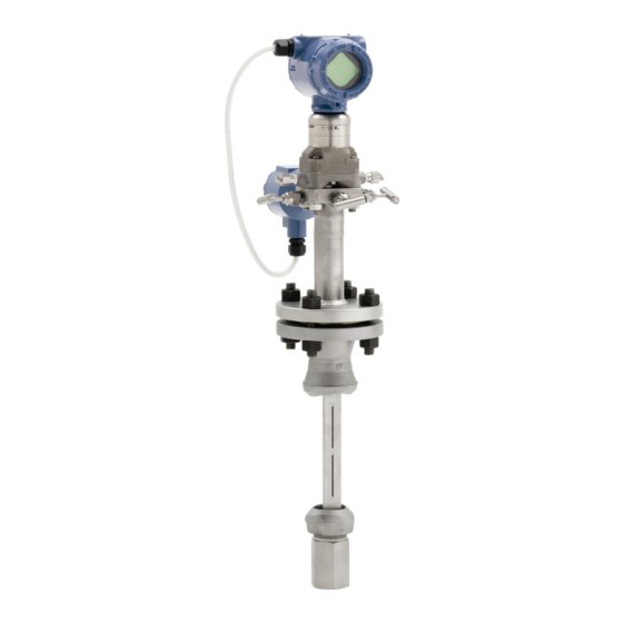
00825-0100-4809, Rev DB Flanged 485 Annubar December 2009 © 2009 Rosemount Inc. All rights reserved. All marks property of owner. Rosemount and the Rosemount logotype are registered trademarks of Rosemount Inc. Rosemount Inc. Emerson Process Management GmbH & Co. OHG... - Page 3 Quick Installation Guide 00825-0100-4809, Rev DB Flanged 485 Annubar December 2009 485 Annubar Flange Assembly Exploded View Transmitter Transmitter and housing are shown for clarity purposes – only supplied if ordered. Coplanar Flange with Drain Vents O-Rings (2) Direct Mount Transmitter...
- Page 4 Quick Installation Guide 00825-0100-4809, Rev DB Flanged 485 Annubar December 2009 1: L OCATION AND RIENTATION Correct orientation and straight run requirements must be met for accurate and repeatable flow measurements. Refer to Table 1 for minimum pipe diameter distances from upstream disturbances.
- Page 5 • Row 6 in Table 1 applies to gate, globe, plug, and other throttling valves that are partially opened, as well as control valves. Misalignment 485 Annubar installation allows for a maximum misalignment of 3°. Figure 1. Misalignment ±3° ±3°...
- Page 6 Quick Installation Guide 00825-0100-4809, Rev DB Flanged 485 Annubar December 2009 CONTINUED Horizontal Orientation For proper venting and draining, the sensor should be located in the upper half of the pipe for air and gas applications. For liquid and steam applications, the sensor should be located in the bottom half of the pipe.
- Page 7 Quick Installation Guide 00825-0100-4809, Rev DB Flanged 485 Annubar December 2009 CONTINUED Vertical Orientation The sensor can be installed in any position around the circumference of the pipe, provided the vents are positioned properly for bleeding or venting. Optimal results for liquid or steam are obtained when flow is up.
- Page 8 Quick Installation Guide 00825-0100-4809, Rev DB Flanged 485 Annubar December 2009 2: D RILL OLES INTO 1. Determine the sensor size based on the probe width (see Table 2). 2. Depressurize and drain the pipe. 3. Select the location to drill the hole.
- Page 9 5. Compare the numbers obtained in steps 3 and 4. Small discrepancies can be compensated for with the fit-up of the mounting hardware. Large discrepancies may cause installation problems or error. Figure 8. Fit-up check for 485 Annubar with Opposite-Side Support Liquid or Steam Port A...
- Page 10 Quick Installation Guide 00825-0100-4809, Rev DB Flanged 485 Annubar December 2009 4: W OUNTING ARDWARE 1. Center the flanged assembly over the mounting hole, gap -in. (1,6 mm), and measure the distance from the outer diameter of the pipe to the face of the flange. Compare this to Table 3 and adjust the gap as necessary.
-
Page 11: Step 6: Mount The Transmitter
Quick Installation Guide 00825-0100-4809, Rev DB Flanged 485 Annubar December 2009 5: I NSERT THE NNUBAR 1. Align the flow arrow on the head with the direction of flow. Assemble the bar to the mounting flange using a gasket, bolts, and nuts. - Page 12 Quick Installation Guide 00825-0100-4809, Rev DB Flanged 485 Annubar December 2009 CONTINUED The following restrictions and recommendations apply to impulse piping location: 1. Impulse piping that runs horizontally must slope at least one inch per foot (83 mm/m). • Slope downward (toward the transmitter) for liquid and steam applications •...
- Page 13 Quick Installation Guide 00825-0100-4809, Rev DB Flanged 485 Annubar December 2009 CONTINUED Table 4. Description of Impulse Valves and Components Name Description Purpose Components Transmitter Reads Differential Pressure Manifold Isolates and equalizes electronics Manifold and Impulse Valves Primary Sensor High and low side pressure process connections.
- Page 14 Quick Installation Guide 00825-0100-4809, Rev DB Flanged 485 Annubar December 2009 CONTINUED Steam or Liquid Service (below 600 °F (315 °C)) Mount the transmitter below the process piping, adjust 10 to 15 degree above direct vertical down. Route the impulse piping down to the transmitter and fill the system with water through the two cross fittings.
- Page 15 European Directive Information The EC declaration of conformity for all applicable European directives for this product can be found on the Rosemount website at www.rosemount.com. A hard copy may be obtained by contacting our local sales office. European Pressure Equipment Directive (PED) (97/23/EC) Rosemount 485 Annubar —...
- Page 16 Quick Installation Guide 00825-0100-4809, Rev DB Flanged 485 Annubar December 2009...
Need help?
Do you have a question about the 485 Annubar and is the answer not in the manual?
Questions and answers