
Subscribe to Our Youtube Channel
Related Manuals for Fluke 9062


Summary of Contents for Fluke 9062
- Page 1 ® 9062 Motor and Phase Rotation Indicator Users Manual PN 2438554 April 2005 © 2005 Fluke Corporation. All rights reserved. Printed in China All product names are trademarks of their respective companies.
- Page 2 LIMITED WARRANTY AND LIMITATION OF LIABILITY This Fluke product will be free from defects in material and workmanship for two years from the date of purchase. This warranty does not cover fuses, disposable bat- teries, or damage from accident, neglect, misuse, alteration, contamination, or ab- normal conditions of operation or handling.
-
Page 3: Table Of Contents
Contacting Fluke ....................1 Unpacking the 9062 .................... 2 Safety Information ....................2 Symbols....................... 5 Elements of the 9062 ..................6 Using the Motor & Phase Rotation Indicator............7 Determine Rotary Field Direction ..............7 Non-Contact Rotary Field Indication ............... 9 Determine the Motor Connection .............. - Page 4 List of Tables Table Title Page Symbols ....................... 5 Reliable Motor Test Requirements .............. 11 List of Figures Figure Title Page The 9062 Motor and Phase Rotation Indicator..........6 Phase Indication Table ................8 Motor Rotation ..................... 10 Battery Replacement ................... 16...
-
Page 5: Introduction
9062 Introduction The Fluke 9062 Motor and Phase Rotation Indicator (hereafter referred to, “the 9062”) is a handheld, battery-operated instrument designed to detect the rotary field of three-phase systems and determine motor-rotation direction. Contacting Fluke To contact Fluke, call one of the following telephone numbers:... -
Page 6: Unpacking The 9062
9062 Users Manual Unpacking the 9062 The 9062 ships with the following items: • 3 test leads • 3 test probes • 3 alligator clips • 9 V battery • Users Manual If an item is damaged or missing, contact the place of purchase immediately. - Page 7 Inspect the test leads for damaged insulation or exposed metal. Check test lead continuity. Damaged leads must be replaced. Do not use the 9062 if it looks damaged. • Be careful when working above 30 V ac rms, 42 V ac peak and 60 V dc.
- Page 8 Verify operation on a known source prior to measuring hazardous voltages (voltages above 30 V ac rms, 42 V ac peak and 60 V dc). • Do not use the 9062 with any of the parts removed. • Do not use the 9062 around explosive gas, vapor, or dust.
-
Page 9: Symbols
Motor & Phase Rotation Indicator Symbols Symbols The following symbols appear on the 9062 or in this manual. Table 1. Symbols Risk of electric shock Earth Risk of Danger. Important information. AC or DC See manual. Hazardous voltage. Recycling information Equipment protected by double or Conforms to EU directives. -
Page 10: Elements Of The 9062
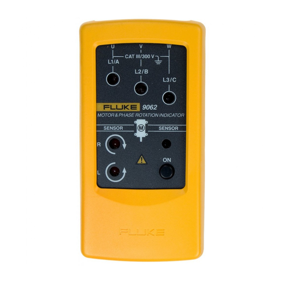
Indicators, buttons, and jacks are shown in Figure 1. Test lead input jack L1, L2, L3 Indicators Orientation Symbol Clockwise Rotation LCD Indicator ON/OFF indicator Counter-Clockwise Rotation LCD Indicator ON/OFF button bby03f.eps Figure 1. The 9062 Motor and Phase Rotation Indicator... -
Page 11: Using The Motor & Phase Rotation Indicator
Determine Rotary Field Direction To determine the rotary field direction: Connect one end of the test leads to the 9062. Make sure the L1, L2, and L3 test leads are connected to the corresponding input jacks. Connect the test probes to the other end of the test leads. -
Page 12: Phase Indication Table
9062 Users Manual bby01f.eps Figure 2. Phase Indication Table (shown on the rear of the 9062) -
Page 13: Non-Contact Rotary Field Indication
Either the Clockwise or Counter Clockwise Rotary indicator illuminates showing the type of rotary field direction present. Note The Indicator will not operate with engines controlled by frequency converters. The bottom of the 9062 should be oriented towards the drive shaft. See the Orientation Symbol on the 9062. -
Page 14: Motor Rotation
9062 Users Manual bby02f.eps Figure 3. Motor Rotation... -
Page 15: Reliable Motor Test Requirements
Motor & Phase Rotation Indicator Using the Motor & Phase Rotation Indicator See Table 2 for the minimum motor diameter and number of pole pair to obtain a reliable test result. Table 2. Reliable Motor Test Requirements Min. ∅ of Rotary Number of Rotary Field (1/min) at Angle Between Number... -
Page 16: Determine The Motor Connection
Users Manual Determine the Motor Connection Connect one end of the test leads to the 9062. Make sure the L1, L2, and L3 test leads are connected to the corresponding jack. Connect the alligator clamps to the other end of the test leads. -
Page 17: Magnetic Field Detection
This section provides basic maintenance information. W Caution To avoid damaging the 9062: • Do not attempt to repair or service the 9062 unless qualified to do so. • Make sure that the relevant calibration, performance test, and service information is being used. -
Page 18: Replacing And Disposing Of The Batteries
M appears. Note The 9062 contains alkaline batteries. Do not dispose of these batteries with other solid waste. Used batteries should be disposed of by a qualified recycler or hazardous materials handler. Contact your authorized Fluke Service center for recycling... - Page 19 Motor & Phase Rotation Indicator Maintaining the 9062 The 9062 uses a 9 V battery (supplied). To replace the battery, follow these steps and refer to Figure 4: Disconnect test leads from any power source. Remove the holster. Place the 9062 face down on a nonabrasive surface and loosen the battery-door screw with a flat-blade screwdriver.
-
Page 20: Battery Replacement
9062 Users Manual bby04f.eps Figure 4. Battery Replacement... -
Page 21: Specifications
Motor & Phase Rotation Indicator Specifications Specifications Safety Specifications Electrical Safety Environmental Meets DIN VDE 0411, IEC 61010 DIN Operating Temperature VDE 0413-7, EN 61557-7, IEC 61557-7 0 °C to +40 °C Maximum Operating Voltage (U Operating Altitude 400 V AC for all ranges 2000 m Protection Level Pollution Degree... - Page 22 9062 Users Manual Determine Rotary Field Direction Non-Contact Rotary Field Indication Nominal Voltage Rotary Direction Frequency Range (f 1 to 400 V AC 2 to 400 Hz Nominal Voltage Phase Indication Determine the Motor Connection 120 to 400 V AC...
Need help?
Do you have a question about the 9062 and is the answer not in the manual?
Questions and answers