Table of Contents
Advertisement
Advertisement
Table of Contents

Related Manuals for TECSYSTEM NT511 AD


Summarization of Contents
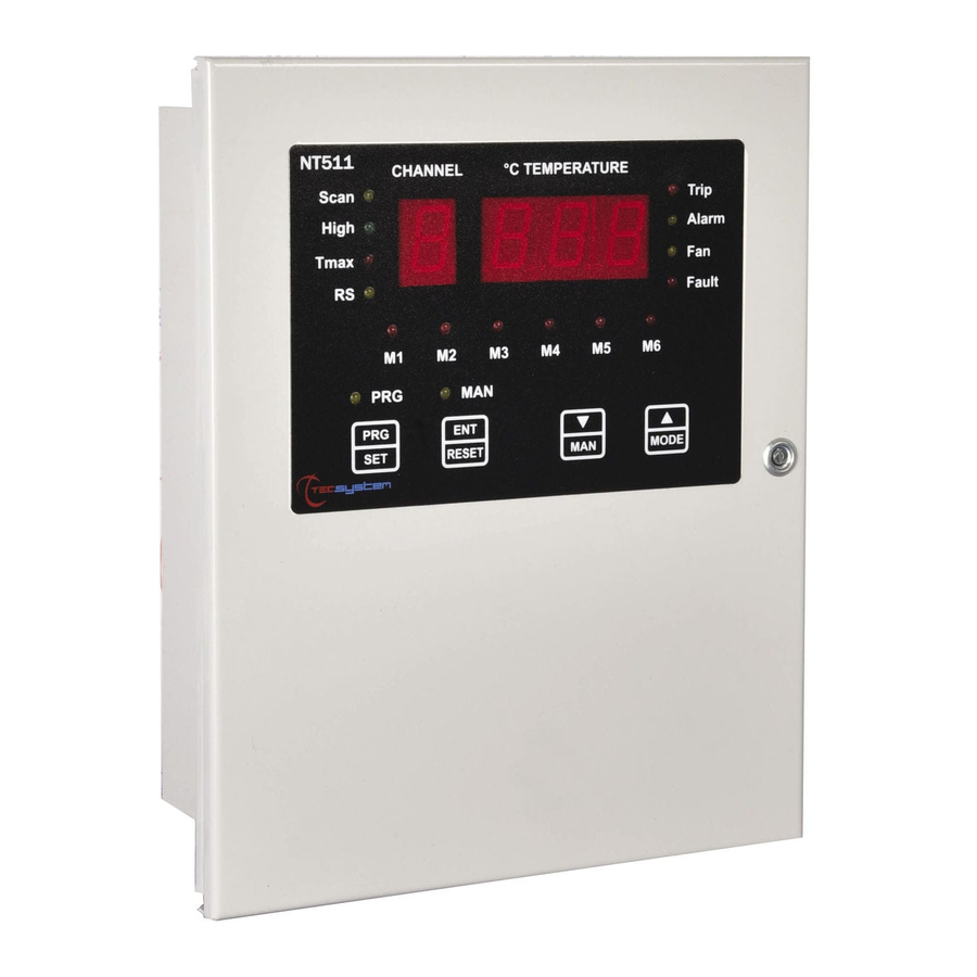
FRONT PANEL
DISPLAY
Describes the unit's displays and display modes (SCAN, HIGH, T.MAX).
OPERATING PROGRAM CONTROL
Explains how to access and use the programming mode using the PRG key.
LED TEST
Describes the LED test performed during unit power-on and parameter display.
ALARM RELAY SILENCING
Explains how to silence the ALARM signal using the RESET key.
ELECTRICAL CONNECTIONS
Pt100 CONNECTION EXAMPLE
Illustrates how to connect Pt100 sensors, including wiring colors and cable specifications.
POWER SUPPLY
Details the 230Vac power supply, ground connection, and precautions for replacement.
ALARMS AND VENTILATION
Explains how to perform electrical connections and describes the behavior of ALARM and TRIP relays.
FAULT CONTACT OPERATION
Details the operation of the FAULT contact (NC/NO) based on system status.
PROGRAMMING
PROGRAMMING NOTES
Provides notes on programming abandonment, unit behavior during programming, and error messages.
TEMPERATURE SENSORS
Describes the connection and regulations for Pt100 thermometric sensors.
MEASUREMENT SIGNAL TRANSFER
Details rules for connecting Pt100 sensors and extension cables to prevent interference and ensure accuracy.
TEMPERATURE SENSOR DIAGNOSTICS
Explains Fcc, Foc, Fcd fault indications, CAL message, and data memory diagnostics.
PROGRAMMED DATA DIAGNOSTICS
Describes the 'Ech' message indicating memory corruption and default parameter loading.
TEMPERATURE DIAGNOSTICS
Explains how ALARM and TRIP relays activate based on temperature thresholds.
COOLING FAN CONTROL
Details the two methods for controlling cooling fans based on temperature and manual activation.
RS485 MODBUS OUTPUT
INTRODUCTION TO THE MODBUS INSIDE MODULE
Introduces the Modbus expansion module and its capabilities for RS485 data transfer.
OPERATING NOTES
Covers essential notes for correct RS485 network setup and operation parameters.
DATA TRANSMISSION ON MODBUS NETWORK
Explains how data is transmitted on the Modbus network and module slave mode.
RS485 ELECTRICAL CONNECTIONS
Provides recommendations for connecting RS485 twisted pair cables and grounding.
DATA FRAME
Describes the structure of asynchronous transmission frames used in Modbus.
DATA PACKET
Outlines the structure of Modbus master requests and slave answers.
FUNCTION CODE
Details the supported Modbus function codes (3, 16) for reading and writing registers.
CODE 3 (10)
Explains the request and answer format for Modbus function code 3 (holding register reading).
CODE 16 (10)
Explains the request and answer format for Modbus function code 16 (register multiple writing).
NOTES FOR REMOTE PROGRAMMING
Provides crucial notes for programming NT511 units remotely via Modbus.
ERROR CODES (exception codes)
Lists and explains Modbus error codes that may be returned in response to a request.
POLLING FREQUENCY
Recommends optimal polling frequencies for Modbus communication to avoid system overload.
MODBUS MAPPING TABLE
Details the Modbus registers, their addresses, data types, and primary tables.
CRC CALCULATION
PARAMETER DESCRIPTION
Lists and describes parameters used in Modbus communication, like registers and addresses.
ALGORITHM
Details the step-by-step algorithm used for CRC calculation.
OUTPUT 4.20mA
Pt100 EXTENSION CABLE TECHNICAL SPECIFICATIONS
Lists the technical specifications for the Pt100 extension cable.
Need help?
Do you have a question about the NT511 AD and is the answer not in the manual?
Questions and answers