TECSYSTEM NT538 Instruction Manual
Hide thumbs
Also See for NT538:
- Instruction manual (30 pages) ,
- Instruction manual (13 pages) ,
- Instruction manual (30 pages)
Table of Contents
Advertisement
Quick Links
Advertisement
Table of Contents

Related Manuals for TECSYSTEM NT538


Summary of Contents for TECSYSTEM NT538
- Page 1 Cross Reference RA Part Number PP8704 TECSYSTEM S.r.l ® INSTRUCTION MANUAL NT538 TECSYSTEM S.r.l. Via Cristoforo Colombo, 5/C 20094 Corsico (Milan) phone +39-0248601011 / 024581861 Fax: +39-0248600783 http://www.tecsystem.it R.1 08/09/05 NT538 P8 V4-R1.4 protection relays...
- Page 2 TECSYSTEM S.r.l ® INNOVATIONS INTRODUCED WITH THE NT538 New hardware and software for a further improvement of immunity to disturbances. Reading rate increasing, indispensable for applications where fast temperature variations must be monitored. Intelligent control of alarm detecting relays which is able to exclude possible overtemperatures caused by an external disturbance without causing working prob- lems or manual reset conditions.
- Page 3 Maximum reached temperatures, alarm storage and sensor fault. • Frontal alarm reset push button DIMENSIONS SOFTWARE RELEASE • • 96 x 96 mm-DIN43700– depth 140 mm P8 V4-R.1.4 (terminal box included) • Panel cut-out 92 x 92 mm NT538 P8 V4-R1.4 protection relays...
-
Page 4: Power Supply
Firmly tighten the device with the enclosed fixing blocks. 3) POWER SUPPLY NT538 control device has an UNIVERSAL supply, i.e. it can be indifferently fed from 24 to 240 Vac-dc, regardless of polarities in Vdc. This peculiarity is obtained using a new-concept and new-designed tested feeder, which relieves the technician of each concern for the correct supply Vac or Vdc. - Page 5 Eliminate Ech indication by pressing RESET and run programming to insert desired val- ues. Finally turn off and turn on again the unit to verify the correct memory working; in case it is damaged and Ech still appears, please return the monitoring unit to TECSYSTEM for repair. 9) TEMPERATURE DIAGNOSTIC If one of the temperature sensor detects a temperature higher than 1°C compared to set...
-
Page 6: Cooling Fan Control
For this operation, shortly press TEST key; all displays turn on for 2 seconds. If one of the LED’s should not work, we kindly ask you to return the monitoring unit to TECSYSTEM (Led RS is not available on monitoring units without optional module) -
Page 7: Alarm Relay Test
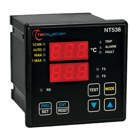
18) FRONT PANEL Message and tem- perature display Display mode Alarm selected channel Selected Data channel transmission (option) Prg/RelaysTest mode Keyboard NT538 P8 V4-R1.4 protection relays... - Page 8 ENT it appears “ERR”, it means that one of the following mistakes has been made: ALARM ≥ TRIP or FAN-OFF ≥ FAN-ON. Press PRG to return to step 1 and correct the data. After 1 minute of keyboard no-operation, programming is left without data storage. NT538 P8 V4-R1.4 protection relays...
-
Page 9: Warranty
In this case TECSYSTEM S.r.l. do not answer for damages caused by faulty or defec- tive monitoring units. All the deliveries (go and back) as well as the repair and servicing costs for the device will be at Customer’s expenses, reckoned according to ANIMA, Col. - Page 10 When a channel is in Fault for FCD, relevant Alarm and Trip signalling are inhibited in order to report just the anomaly for the too fast rise in temperature. Press Reset to cancel FCD signalling for all the channels and to reset relays fault. NT538 P8 V4-R1.4 protection relays...
- Page 11 ALARM RELAY OUTPUTS 10 11 ALARM TRIP FAULT Pt100 POWER SUPPLY WHITE 24-240 VAC-VDC ESPANSION MODULE OUTPUT GND RX GND TX If TX is fore- seen on the module GND TX GND RX EXPANSION NT538 MODULE NT538 P8 V4-R1.4 protection relays...
- Page 12 This device has passed a test at the origin, according to the following procedure: N° Description Mounting card check Input working check Relay contacts and output check Push-button working check Check lamp Calibration at 0 and 200°C Software working check Burn-in min. 24h Date: …………… NT538 P8 V4-R1.4 protection relays...
Need help?
Do you have a question about the NT538 and is the answer not in the manual?
Questions and answers