Table of Contents
Advertisement
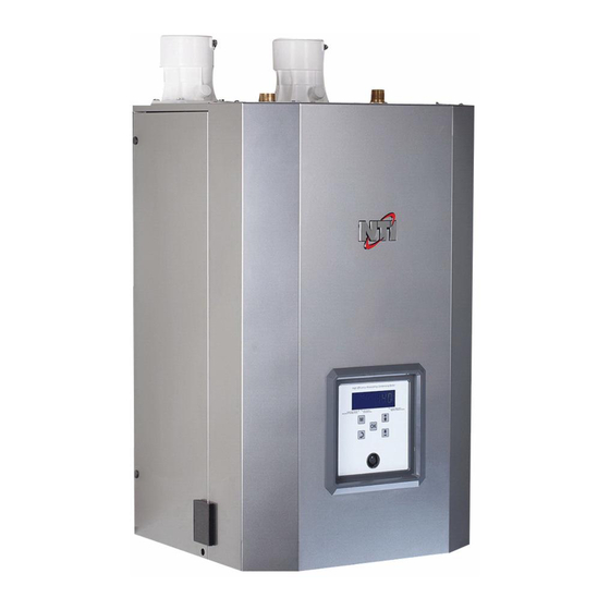
FTV Boiler
Model Numbers: FTV110, FTV110C, FTV150, FTV150C, FTV190 & FTV190C
Version Date: 2018-03-12
INSTALLATION AND OPERATION MANUAL
TABLE OF CONTENTS
1.0
Introduction ................................................................................................................ 3
2.0
Specifications .............................................................................................................. 6
3.0
Boiler Location .......................................................................................................... 7
4.0
General Venting ....................................................................................................... 10
5.0
Vent/Air-Inlet Termination Clearances ..................................................... 25
6.0
Condensate Drain .................................................................................................... 27
7.0
Installing Gas Piping .............................................................................................. 29
8.0
Lighting The Boiler ................................................................................................. 31
9.0
Gas Valve And Burner Set-Up ............................................................................ 34
10.0 BOILER AND HEATING SYSTEM PIPING ................................................................... 37
11.0 DOMESTIC HOT WATER (DHW) PIPING – COMBI ONLY ....................................... 49
12.0 FIELD WIRING ................................................................................................................. 51
13.0 CASCADE INSTRUCTIONS ............................................................................................ 54
14.0 WIRING SCHEMATICS ................................................................................................... 57
15.0 INSTALLATION CHECKLIST ........................................................................................ 59
16.0 ANNUAL MAINTENANCE AND INSPECTION ........................................................... 60
17.0 DISPLAY MENU GUIDE ................................................................................................. 62
18.0 TROUBLESHOOTING ..................................................................................................... 75
19.0 PARTS LIST ...................................................................................................................... 78
HAZARD SYMBOLS AND DEFINITIONS
unit may result in property damage, serious injury to occupants, or possibly death.
Danger Sign: Indicates a hazardous situation which, if not avoided, will
result in serious injury or death.
Warning Sign: Indicates a hazardous situation which, if not avoided,
could result in serious injury or death.
Caution Sign plus Safety Alert Symbol: Indicates a hazardous situation
which, if not avoided, could result in minor or moderate injury.
Caution Sign without Safety Alert Symbol: Indicates a hazardous
situation which, if not avoided, could result in property damage.
Notice Sign: Indicates a hazardous situation which, if not avoided,
could result in property damage.
This Boiler must be installed by a licensed and trained Heating
Technician or the Warranty is Void. Failure to properly install this
H
NTI # 85939
Advertisement
Table of Contents

Related Manuals for NTI FTV110


Summary of Contents for NTI FTV110
- Page 1 FTV Boiler Model Numbers: FTV110, FTV110C, FTV150, FTV150C, FTV190 & FTV190C Version Date: 2018-03-12 INSTALLATION AND OPERATION MANUAL TABLE OF CONTENTS INTRODUCTION ........................ 3 SPECIFICATIONS ......................6 BOILER LOCATION ......................7 GENERAL VENTING ....................... 10 VENT/AIR-INLET TERMINATION CLEARANCES ............. 25 CONDENSATE DRAIN ....................
- Page 2 │ Warnings FTV I&O Manual Read Before Proceeding If you do not follow these instructions exactly, a fire or explosion may result causing property damage, serious injury or death. FOR YOUR SAFETY, READ BEFORE OPERATING_ A) This boiler does not have a pilot. It is equipped with an ignition device which automatically lights the burner.
-
Page 3: Introduction
1.0 INTRODUCTION General Installation Requirements The installation of your NTI FTV gas boiler must conform to the requirements of this manual, your local authority, and the National Fuel Gas Code ANSI Z223.1 and or CAN/CGA B149 Installation Codes. Where required by the Authority, the installation must conform to the standard for “Controls and Safety Devices for Automatically Fired Boilers ANSI/ASME CSD-1.”... - Page 4 LP gas be provided with an approved means of removing unburned gases from the room. Check your local codes for this requirement. Natural Gas to LP Conversion Kit Model Natural Gas to LP Conversion Kit (part no.) LP-Venturi Insert (part no.) FTV110 & FTV110C 85995-1 85989 FTV150 & FTV150C 85446-1 85536 FTV190 &...
- Page 5 │Introduction FTV I&O Manual IN THE STATE OF MASSACHUSETTS ONLY (a) For all horizontally vented gas fueled equipment installed in every dwelling, building or structure used in whole or in part for residential purposes, including those owned and operated by the Commonwealth and where the side wall exhaust vent termination is less than seven (7) feet above finished grade in the area of the venting, including but not limited to decks and porches, the following requirements shall be satisfied: INSTALLATION OF CARBON MONOXIDE DETECTORS At the time of installation of the side wall...
-
Page 6: Specifications
│ Specifications FTV I&O Manual 2.0 SPECIFICATIONS Table 2-1 FTV Specifications DESCRIPTION FTV110 FTV150 FTV190 FTV110C FTV150C FTV190C CSA Input Modulation 11 - 110 15 - 150 19 - 190 11-110 15 - 150 19 - 190 [MBH] DOE Heating Capacity... -
Page 7: Boiler Location
│Boiler Location FTV I&O Manual 3.0 BOILER LOCATION In all cases, the FTV boiler must be installed indoors in a dry location where the ambient temperature must be maintained above freezing and below 100F [38C]. All boiler components must be protected from dripping, spraying water, or rain during operation and servicing. - Page 8 │ Boiler Location FTV I&O Manual Figure 3-1 Closet Installation, Minimum Clearances Top ventilation opening Max. 6” below ceiling / top Min. 1” clearance for hot water and vent pipes Ventilation air opening per 1000 Btu/hr, min. 100in Top = 12” Removable surface / closet door Ventilation air opening...
- Page 9 │Boiler Location FTV I&O Manual Figure 3-2 Wall Mounting Instructions Failure to follow instructions may Leave the Top Wall-mount Bracket (A) intact result in fire, serious injury, or death. and remove the Bottom Wall-mount Bracket (B) that is attached to the bottom-back of the This unit requires two people to lift it boiler.
-
Page 10: General Venting
│ General Venting FTV I&O Manual 4.0 GENERAL VENTING The FTV is certified as a “Category IV” boiler requiring a “Special Venting System” designed for pressurized venting. The Exhaust Vent must be piped to the outdoors, using the vent materials and rules outlined in this section. - Page 11 │General Venting FTV I&O Manual Direct Vent Installation (Best Practice) When installed as a Direct Vent boiler the combustion air-inlet must also be piped directly to the outdoors using the methods described in this section and in accordance with the National Fuel Gas Code, ANSI Z223.1 (U.S.) or CSA B149.1 (Canada) and local requirements.
- Page 12 │ General Venting FTV I&O Manual Mandatory Pre-commissioning Procedure for Plastic Venting (PVC or CPVC) Do not apply power to the boiler prior to Step 4 in the Mandatory Pre-commissioning Procedure for Plastic Venting. 1) Working with the power turned off to the boiler, completely install the vent and air-intake system, securely cementing joints together.
- Page 13 Polypropylene 4.17” (SS) Lower Gasket – 3” OD Seal use with Stainless Steel Figure 4-2 (b) Exhaust Vent Connection – FTV110(C) CPVC/PP/SS Exhaust Pipe With 1/8” bevel to prevent damage to gasket. When venting with PVC, use 5” long CPVC Transition Pipe...
- Page 14 │ General Venting FTV I&O Manual Figure 4-3(a) FTV110(C) Figure 4-3(b) FTV110(C) Near Boiler Venting (PVC) Near Boiler Venting (CPVC) Swing Joint Swing Joint to attain slope in to attain slope in horizontal runs horizontal runs PVC Air-inlet Pipe* PVC Air-inlet Pipe*...
- Page 15 │General Venting FTV I&O Manual Figure 4-3(a) FTV150-190(C) Figure 4-3(b) FTV150-190(C) Near Boiler Venting (PVC) Near Boiler Venting (CPVC) Swing Joint Swing Joint to attain slope in to attain slope in horizontal runs horizontal runs PVC Exhaust Vent CPVC Exhaust Vent PVC Air-inlet Pipe* PVC Air-inlet Pipe* PVC Coupling...
- Page 16 Number of Elbows (90’s or 45’s) and Equivalent Feet Pipe Size Models Length (ft.) (in.) FTV110/110C & FTV150/150C Only All FTV Models Notes: See WARNING below. Minimum length of each the exhaust vent and combustion air-inlet piping is 6 feet equivalent.
- Page 17 Kits certified with the FTV are listed in Table 4-5 and available from the manufacturers listed in Table 4-4. Kits with an NTI part number listed in Table 4-5, are available directly from NTI. Table 4-4 Optional Termination Kit OEMs...
- Page 18 Table 4-5 Optional Vent Termination Kits Vent Option Vent Vent Material Description Supplier p/n Figure Size Compatibility Roof Wall 2” 196984 (NTI p/n 85062) IPEX Low Profile 4-4(b), 4-6(c) (Wall) 3” 196985 (NTI p/n 84357) 2” 196125 PVC/CPVC IPEX Concentric 4-4(c), 4-5(c), ...
- Page 19 │General Venting FTV I&O Manual Sidewall Venting Options – Direct Vent Installation Figure 4-4 (a) Two-pipe Termination (Sidewall) Figure 4-4 (b) Low Profile Termination (Sidewall) Location of exhaust and air-inlet Location of exhaust and air-inlet connections vary between connections vary between models, see Figure 4-3.
- Page 20 │ General Venting FTV I&O Manual Roof Venting Options – Direct Vent Installation Figure 4-5 (a) Two-pipe Termination (Roof) Figure 4-5 (b) Two-pipe Termination (Roof/Sidewall) Location of exhaust and air-inlet Location of exhaust and air-inlet connections vary between connections vary between models, see Figure 4-3.
- Page 21 │General Venting FTV I&O Manual Sidewall Termination Details – Direct Vent Installation Figure 4-6 (b) IPEX Concentric Termination Figure 4-6 (a) Two-Pipe Termination (Sidewall) (Sidewall) Horizontal 4-12” or greater than 36” Refer to documentation included with termination kit for complete installation instructions. Exhaust Exhaust Exhaust...
- Page 22 │ General Venting FTV I&O Manual Roof Termination Details – Direct Vent Installation Figure 4-7 (a) Two-Pipe Termination (Roof) Figure 4-7 (b) IPEX Concentric Termination (Roof) Exhaust Refer to documentation included with termination kit for Vent Screen complete installation instructions. Vent pipe piece to retain vent screen Vent pipe piece to...
- Page 23 Combustion air containing chemicals such as chloride, fluoride, bromine or iodine or dust and debris will cause corrosion damage of the heat exchanger voiding your NTI warranty. Refer to Table 4-1 for a list of corrosive products and contaminants sources to avoid.
- Page 24 │ General Venting FTV I&O Manual Figure 4-8 Venting Below Grade For installations that exit the wall below grade: Exhaust 1. Excavate site to a point below where the pipes are to exit as shown. 2. Ensure the wall is fully sealed where the pipes Air-inlet penetrate.
-
Page 25: Vent/Air-Inlet Termination Clearances
│Condensate Drain FTV I&O Manual 5.0 VENT/AIR-INLET TERMINATION CLEARANCES The quick reference table below is to be read in conjunction with the numbered notes as indicated, Figures 5-1 and 5-2, and the Venting Rules and Guidelines in Section 4.0. The instructions detailed in this section are a combination of FTV specific and National Gas Code restrictions. -
Page 26: Condensate Drain
Condensate Drain│ FTV I&O Manual Figure 5-1 Termination Clearance Quick Reference Diagram (See Table 5-1) Illustrations of Termination Clearances Figure 5-2 Sidewall Termination (See Table 5-1) Clearances “F” and “G” Canada – Minimum 3 ft. [915 mm] The US – Minimum 1 ft. [305 mm] Two-Pipe Termination Clearance “Q”... -
Page 27: Condensate Drain
│Condensate Drain FTV I&O Manual 6.0 CONDENSATE DRAIN The FTV boilers produce liquid condensate in the heat exchanger and venting system as a product of combustion. Steps must be taken to ensure condensate does not collect in the venting system; therefore, all exhaust piping must slope back to the boiler a minimum ¼... - Page 28 Condensate Drain│ FTV I&O Manual Figure 6-1 Condensate Drain Piping Inlet Gasket Inlet Boiler Condensate Drain Condensate Trap Outlet Outlet Gasket Cleanout Cap Ball-float Outlet Gasket Outlet Retaining Nut Corrugated Outlet Tube Inlet Retaining Nut firmly tightened ...
-
Page 29: Installing Gas Piping
Ensure that: The gas line connection to the boiler does not apply any weight to the gas valve. NTI recommends using approved flexible gas piping (if acceptable by local codes) to connect the boiler to the gas supply (see Figure 7-1 for details). -
Page 30: Lighting The Boiler
Lighting the Boiler│ FTV I&O Manual When performing a pressure test on the gas line piping, be sure the boiler is disconnected or isolated if the test pressure is expected to exceed 1/2 PSI (14 in. w.c.), as damage to the gas valve could occur resulting in fire, property damage, serious injury or death. -
Page 31: Lighting The Boiler
│Lighting the Boiler FTV I&O Manual 8.0 LIGHTING THE BOILER Before Start-up refer to Mandatory Pre-commissioning Procedure for Plastic Venting in Section 4.0. Failure to follow these instructions can result in explosions, injury or death. Prior to turning the gas supply on and lighting the boiler, ensure all aspects of the installation are complete and in conformance with the instructions provided in this manual, including the Vent/Air-inlet, Condensate Drain, and System Water Piping. - Page 32 Volts potential which would result in an EXTREME ELECTRICAL SHOCK possibly causing serious injury or death. If the unit fails to light consistently and smoothly, contact NTI for technical assistance at 1-800-688-2575. Never allow the boiler to operate if the ignition or operation of the burner is rough or erratic.
- Page 33 │Lighting the Boiler FTV I&O Manual Turning Off the Boiler 1. Set the thermostat to the lowest setting, and then turn off all power to the boiler. 2. Turn the gas shutoff valve to the off position.
-
Page 34: Gas Valve And Burner Set-Up
Table 9-2 Minimum and Maximum Modulation Rates Input Rate (MBH) Appliance Min. Modulation Rate Max. Modulation Rate Model Number (RPM) (RPM) Max * 1620 7620 FTV110 1860 8040 1620 7620 FTV110C 1860 8040 FTV150 NG/LP 1740 8220 FTV150C... - Page 35 1. Operate the unit at the maximum modulation rate, see Table 9-2. NOTICE: the modulation rates must be adjusted for models FTV110 & FTV110C operating with Propane; this is accomplished by adjusting the Appliance Number to the value provided in Table 9-2 – see section titled “Controller Replacement Instructions”...
- Page 36 │ Gas Valve and Burner Set-up FTV I&O Manual Figure 9-1 Gas Valve and Venturi Assembly (FTV150 Illustrated) Line Pressure Test Port Throttle / Input Adjustment Screw Gas Valve Manifold Pressure Test Port DO NOT Adjust Venturi...
-
Page 37: Boiler And Heating System Piping
Failure to follow the instructions provided in this section will void the NTI warranty and may result in property damage, fire, serious injury or death. - Page 38 A list of approved inhibitors is provided below. • Rhomar Pro-tek 922 • Sentinel X100 • Fernox Protector F1 (NTI part no. 83448) Table 10-1 Boiler System Cleansers and Corrosion Inhibitors Parameter Range Information The total pH scale ranges from 1 to 14, with 7 considered to 7 to 9 be neutral.
- Page 39 (see Section 12.0 – Field Wiring). NTI offers the following LWCO kit p/n 85253. When the installation is complete, TEST THE LWCO to ensure the burner shuts down when the...
- Page 40 │ Boiler and Heating System Piping FTV I&O Manual Near Boiler Piping (Central Heating – CH) Figure 10-2(a) Top (All Models) Figure 10-2(b) Bottom (non-Combi) Auto Air Vent (factory supplied) 30 PSI Relief Valve (factory supplied) Boiler Outlet ¾ in. Brass Street Elbow (factory supplied) Boiler Inlet ¾...
- Page 41 (See Table 10-2 for minimum flow rate requirements). To ensure the minimum flow rate is attained, NTI strongly recommends installing the boiler in a “Primary/Secondary” plumbing configuration utilizing “Closely Spaced Tees” or a “Low Loss Header” to de-couple the Boiler-Primary loop from the System- Secondary loop(s).
- Page 42 │ Boiler and Heating System Piping FTV I&O Manual Figure 10-3 Activating Pressure Bypass Valve (FTV-Combi Only) Manual Bypass Valve – set to MAX (fully clockwise) to activate the Pressure Bypass Valve – mandatory when piping is “Direct to Zones”. Figure 10-4 Available Pump Head (FTV-Combi Internal Pump) Notes: Graph depicts available pump head of FTV-Combi internal pump, after boiler internal flow losses.
- Page 43 10.3 1 in. Figure 10-5 FTV110-190 Head Loss Curve Expansion Tank – The expansion tank must be sized in accordance with the water volume of the system as well as the firing rate of the appliance. It is important to locate the expansion tank, and make-up water fill, on the inlet side of any circulator in the system, as doing so will guarantee the lowest pressure in the system will be at least equal to the tank and make-up water pressure.
- Page 44 Contractor modifications to these instructions may be required, based upon existing piping and system design; consult NTI for required assistance (1-800-688-2575). Figure 10-6 Plumbing Schematic – Single Central Heating Circulator (non-Combi) Figure 10-6 illustrates the basic plumbing requirements for a non-Combi FTV boiler installation with a single Central Heating circulator, and an Indirect Water Heater.
- Page 45 │Boiler and Heating System Piping FTV I&O Manual Figure 10-7 Plumbing Schematic – Multiple Central Heating Circulators (non-Combi) Figure 10-7 illustrates the basic plumbing requirements for a non-Combi FTV boiler installation with multiple Central Heating circulators, and an Indirect Water Heater.
- Page 46 │ Boiler and Heating System Piping FTV I&O Manual Figure 10-8 Plumbing Schematic – Multiple Central Heating Circulators (Combi) Low Loss Header (p/n 85110) Figure 10-8 illustrates the basic plumbing requirements for an FTV-Combi boiler installation with multiple Central Heating circulators.
- Page 47 │Boiler and Heating System Piping FTV I&O Manual Figure 10-9 Plumbing Schematic – Single Central Heating Circulator – Primary/Secondary (Combi) Low Loss Header (p/n 85110) Figure 10-9 illustrates the basic plumbing requirements for an FTV-Combi boiler installation with a single Central Heating circulator in Primary/Secondary configuration.
- Page 48 │ Boiler and Heating System Piping FTV I&O Manual Figure 10-10 Plumbing Schematic – Direct to Zones (Combi) Manual Bypass Valve – set to MAX (fully clockwise). Figure 10-10 illustrates the basic plumbing requirements for an FTV-Combi boiler installation piped “Direct to Zones”. Limited to zone valve (or non-zone circulator) distribution systems with small flow requirements, i.e., systems requiring no more than 6 GPM at 9 ft.
-
Page 49: Domestic Hot Water (Dhw) Piping – Combi Only
│Boiler and Heating System Piping FTV I&O Manual DOMESTIC HOT WATER (DHW) PIPING – COMBI ONLY 11.0 DHW Description of Operation FTV Combi models incorporate a DHW heat exchanger (Brazed Plate) and the controls necessary to heat DHW without requiring a separate water heater. When the internal flow sensor detects potable water flow in excess of 0.3gpm the controller operates in DHW mode, whereby the potable water is heated to the “DHW Setpoint”... - Page 50 │ Boiler and Heating System Piping FTV I&O Manual Figure 11-1 Near Boiler DHW Piping (Combi models) Tempering Valve (Manditory) DHW to Fixtures DHW Outlet (Hot) Cold Water Supply DHW Inlet (Cold) Isolation Valve Y-Strainer Drain Valve (factory supplied) DHW Plumbing (FTV-Combi) DHW Inlet &...
-
Page 51: Field Wiring
│Boiler and Heating System Piping FTV I&O Manual 12.0 FIELD WIRING All wiring must be in accordance with the Canadian Electrical code CSA C22.1 and/or the National Electrical Code ANSI/NFPA 70, local codes, and this manual. NOTICE: the boiler must be electrically grounded. The electrical rating of the FTV is 120V / 1 Phase / 60 Hz / 12A. - Page 52 │ Boiler and Heating System Piping FTV I&O Manual Labeling - Label all wires prior to disconnecting them when servicing controls. Wiring errors can cause improper and dangerous operation. Failure to follow instructions may result in property damage or personal injury. Continuity - Before connecting the line voltage wiring, perform a continuity check between all wires and ground to make sure that there are no electrical leaks that could blow a fuse or damage electrical components.
- Page 53 Tank Thermostat / Sensor (Not Applicable for FTV-Combi models) – Connect the contacts of a DHW Tank Thermostat, or leads of an approved DHW Tank Sensor (NTI p/n: 84632), to terminals 3 and 6. When using a Thermostat, set DHW mode = 2 (menu setting 2-08).
-
Page 54: Cascade Instructions
│ Boiler and Heating System Piping FTV I&O Manual 13.0 CASCADE INSTRUCTIONS The FTV controller has the internal capacity to cascade (lead-lag / stage) up to 16 FTV boilers, without the use of an external controller. Use the instructions detailed in this section to set-up and install the cascade system. FTV-Combi –... - Page 55 Plumbing – install the boilers in parallel in a primary/secondary plumbing configuration as illustrated in Figure 13-1. System Sensor – install a system sensor (NTI p/n: 84010) on the outlet (supply) pipe feeding the heating system, see Figure 13-1. Wire the system sensor to terminals 3 and 4 of the Managing Boiler (left boiler in illustration).
- Page 56 │ Boiler and Heating System Piping FTV I&O Manual Table 13-1 Minimum Pipe Sizes for Multiple Boiler Applications FTV110 FTV150 FTV190 # of Units Pipe Size 2” 1-1/4” 1-1/2” 2” 2” 1-1/2” 2” 2” 2-1/2” 2” 2-1/2” 2-1/2” 3” 2-1/2”...
-
Page 57: Wiring Schematics
│Wiring Schematics FTV I&O Manual 14.0 WIRING SCHEMATICS Figure 14-1 FTV Connection Diagram... - Page 58 │ Wiring Schematics FTV I&O Manual Figure 14-2 FTV Ladder-Logic Diagram...
-
Page 59: Installation Checklist
│Installation Checklist FTV I&O Manual 15.0 INSTALLATION CHECKLIST Installation 1. If operating on Propane Gas, convert boiler using appropriate Conversion Kit. See Table 7-1. 2. Locate the boiler in accordance with Section 3.0 of this manual. 3. Install the Vent/Air-inlet piping in accordance with Sections 4.0 and 5.0 of this manual. Ensure all joints are secured and cemented properly. - Page 60 10. Listen for water flow noises indicating a drop in boiler water flow rate. Important - The hydronic system may need to be flushed to eliminate hard water scale (Use Fernox DS-40 Descaler, NTI PN: 83450). 11. Verify proper operation after servicing.
- Page 61 │Annual Maintenance and Inspection FTV I&O Manual Refractory Ceramic Fibers (RFC) Personal Protective Equipment Recommended - Read the following warnings and handling instructions carefully before commencing any service work in the combustion chamber. The insulating material on the inside of the burner plate contains Refractory Ceramic Fibers and should not be handled without personal protective equipment.
- Page 62 │ Display Menu Guide FTV I&O Manual 17.0 DISPLAY MENU GUIDE Initial Power-up Immediately following power-up of the boiler, the display reads, “conn”, indicating it is connecting to the controller; this is followed by a momentary reading of the display software version, e.g. init 8A94. After which the controller performs a de-air sequence that is designed to purge air from the boiler water.
- Page 63 │Display Menu Guide FTV I&O Manual Figure 17-2 Control Console – Main Screen Water pressure Temperature units Water pressure units Boiler outlet temperature Faucet – flashes OD reset indicator – during DHW demands illuminates when OD Radiator – flashes sensor is enabled during CH demands No flame –...
- Page 64 DHW demands. System sensor temperature – for use only in cascade systems, displays reading from a system temperature sensor, NTI p/n: 84010. When used, the system sensor is only wired to the managing boiler, i.e. boiler with 1-14 S4 switch set to on, and boiler address (Installer Menu setting 2-20) set to 1.
- Page 65 │Display Menu Guide FTV I&O Manual Installer Menu The Installer Menu allows access to all settings for adjustment, as well as viewing of statistical data for troubleshooting. Access the Installer Menu from any screen by pressing the MENU and OK buttons simultaneously until “2-01”...
- Page 66 0 – off; boiler will not attempt to heat DHW in any way. 1 – tank sensor, NTI P/N: 84632, is installed in the indirect water heater and wired to boiler terminals 3 and 6. Tank temperature is adjusted via setting 2-07.
- Page 67 │Display Menu Guide FTV I&O Manual Factory Setting Description Setting Minimum firing rate – allows the installer to increase the minimum modulation/firing rate of the 2-12 boiler; this may be necessary for troubleshooting. Range = 20-44% Maximum firing rate CH – allows the installer to decrease the maximum modulation/firing rate of 2-13 the boiler when operating on a central heat demand;...
- Page 68 │ Display Menu Guide FTV I&O Manual Factory Setting Description Setting Lockout History – displays the last 16 lockouts (Loc) and the time interval between each. The most 2-34 recent lockout is displayed first; see description below. Blocking Error History – displays the last 16 blocking errors (Err) and the time interval between 2-35 each.
- Page 69 │Display Menu Guide FTV I&O Manual Figure 17-5(c) Lockout and Error History Navigation (End) End – indicates that you have reached the end of the recorded lockout or error messages. OK button – press to exit the 2-34 or 2-35 History submenu.
- Page 70 │ Display Menu Guide FTV I&O Manual Figure 17-7 Blocking Error Navigation Err – indicates the boiler has a blocking Error code - see Table error. 17-3 for description. Installer Menu – press and hold MENU and OK buttons to view User Menu –...
- Page 71 UPS (Uninterruptible Power Supply). If source of problem cannot be located, replace controller. Limit Circuit Open (Safety) – see “Loc 5” Controller Malfunction – contact NTI, check field wiring, replace controller. Loc 8-9 Supply Sensor Fault – controller has sensed an invalid reading at the Supply/Outlet sensor; check cable, Loc 10 then replace sensor [see Figure 19-1(a), item 15].
- Page 72 Flame present before ignition – check flame sensor (replace); check condensate drain for blockages; Loc 28 increase post purge setting (Installer Menu setting 2-30). Controller Malfunction – contact NTI, check field wiring, replace controller. Loc 29-30 Flame lost three times during one demand – see Loc 1.
- Page 73 Err 93 Replacement Instructions”; see page 77. Err 94 & up Controller Malfunction – contact NTI, check field wiring, replace controller. Anti-Frost – indicates that the boiler is in Frost Protection. When the controller has sensed a supply or Afro return temperature below 50°F, the Boiler and CH Pumps are switched ON.
- Page 74 FTV I&O Manual Controller Replacement Instructions This section provides important information necessary to successfully replace the boiler controller, NTI 84712, in the event the original controller fails. The replacement controller must be field configured to operate on the FTV boiler model it is being installed on. This is achieved by adjusting the controller’s Appliance Type setting.
-
Page 75: Troubleshooting
│Parts List FTV I&O Manual 18.0 TROUBLESHOOTING Observe the following precautions when servicing the boiler. Failure to comply with these may result in fire, property damage, serious injury or death. Servicing the Boiler Disconnect or shutoff all energy sources to the boiler: 120VAC power, water and gas. ... - Page 76 Indirect Tank with Tank Thermostat (DHW Mode = 2) – recommended setting = 160 to190ºF. FTV Combi – DHW flow rate is too great; report DHW flow rate (User Menu reading 1-05) to NTI. If necessary, restrict overall DHW flow rate.
- Page 77 │Parts List FTV I&O Manual Table 18-1 Thermistor Resistance vs. Temperature Resistance Ohms (Ω) Resistance Ohms (Ω) Temp °F (°C) Temp °F (°C) -22 (-30) 176,133 122 (50) 3,603 -4 (-20) 96,761 131 (55) 2,986 14 (-10) 55,218 140 (60) 2,488 32 (0) 32,650...
-
Page 78: Parts List
│ Parts List FTV I&O Manual 19.0 PARTS LIST For a list of parts that corresponds to the item numbers in the callouts, refer to Table 19-1. Note that some item numbers may appear more than once in the parts list depending on which model number is being referenced. Building Owners - Replacement parts are available from your stocking wholesaler. - Page 79 │Parts List FTV I&O Manual Figure 19-1(b) Heat Exchanger, Water Piping & Sensors (FTV110C, FTV150C, FTV190C)
- Page 80 │ Parts List FTV I&O Manual Figure 19-1(c) Heat Exchanger, Water Piping & Sensors (FTV110, FTV150, FTV190)
- Page 81 │Parts List FTV I&O Manual Figure 19-1(d) Gas Train / Burner Assembly (All FTV)
- Page 82 Parts List FTV I&O Manual Figure 19-1(e) Installation Kit Box (All FTV) Table 19-1 Parts List: FTV Series Item Part # Model Description 85947 FTV110, FTV110C Premix Burner FTV150, FTV150C, 85948 Premix Burner FTV190, FTV190C 85953 FTV110, FTV110C Premix Burner Gasket...
- Page 83 85108 FTV150, FTV150C, FTV190, FTV190C FTV110, FTV110C, 84419 FTV150, FTV150C, Outlet Sensor (Dual) FTV190, FTV190C 85739 FTV110, FTV150, FTV190 Supply Pipe, FTV non-combi FTV110C, FTV150C, 85741 Outlet Pipe to Hydroblock FTV190C FTV110, FTV110C, Auto Air Vent, ½” NPT 84474 FTV150, FTV150C,...
- Page 84 MJ Coupling, 1-1/2” FTV190, FTV190C FTV110, FTV110C, Round Mesh Vent Screen, 2” 82615 FTV150, FTV150C, FTV190, FTV190C 85948-1 FTV110, FTV110C Air-inlet Assembly, FTV110/C FTV150, FTV150C, 85949-1 Air-inlet Assembly, FTV150-190/C FTV190, FTV190C FTV110, FTV110C, 83718 FTV150, FTV150C, Hose Clamp, 1-1/16 to 1-1/2”...
- Page 85 FTV190, FTV190C FTV110, FTV110C Top, FTV110/C FTV150, FTV150C Top, FTV150/C FTV190, FTV190C Top, FTV190/C Bottom Heat Exchanger Support, FTV110/C FTV110, FTV110C FTV150, FTV150C Bottom Heat Exchanger Support, FTV150/C FTV190, FTV190C Bottom Heat Exchanger Support, FTV190/C FTV110, FTV110C Top Heat Exchanger Support, FTV110/C...
- Page 86 │ Parts List FTV I&O Manual Item Part # Model Description FTV110, FTV110C, 84919 FTV150, FTV150C, Gas Valve to Venturi Gasket FTV190, FTV190C FTV110, FTV110C Back, FTV110/C FTV150, FTV150C, Back, FTV150/C, 190/C FTV190, FTV190C FTV110, FTV110C, Tee, Brass, ¾ x ½ x ¾”...
- Page 87 Model Description 85451 FTV150, FTV150C Natural Gas to LP Conversion Instructions 85935 FTV190, FTV190C Natural Gas to LP Conversion Instructions 85995 FTV110, FTV110C LP Conversion Decal 85446 FTV150, FTV150C LP Conversion Decal 85934 FTV190, FTV190C LP Conversion Decal FTV110C, FTV150C, Y-Strainer, Brass, ¾”, 100M Screen...
- Page 88 │ Parts List FTV I&O Manual Visit us online NY Thermal Inc. 30 Stonegate Drive, Saint John, NB E2H 0A4 Canada Technical Assistance: 1-800-688-2575 Fax: 1-506-432-1135 www.ntiboilers.com...
Need help?
Do you have a question about the FTV110 and is the answer not in the manual?
Questions and answers
I have an FTV110C. The boiler is not working and there is a LOC flashing on the display