Table of Contents
Advertisement
Quick Links
©Copyright 2012 Dwyer Instruments, Inc.
DWYER INSTRUMENTS, INC.
P.O. BOX 373 • MICHIGAN CITY, INDIANA 46360, USA
Series PUB Portable Ultrasonic Flowmeter Kit
Installation and Operating Instructions
Printed in USA 9/12
Phone: 219/879-8000
www.dwyer-inst.com
Fax: 219/872-9057
email: info@dwyer-inst.com
Bulletin F-PUB
Version 1.0
Advertisement
Table of Contents
Troubleshooting

Related Manuals for Dwyer Instruments PUB Series


Summary of Contents for Dwyer Instruments PUB Series
- Page 1 Bulletin F-PUB Series PUB Portable Ultrasonic Flowmeter Kit Installation and Operating Instructions ©Copyright 2012 Dwyer Instruments, Inc. Printed in USA 9/12 Version 1.0 DWYER INSTRUMENTS, INC. Phone: 219/879-8000 www.dwyer-inst.com P.O. BOX 373 • MICHIGAN CITY, INDIANA 46360, USA Fax: 219/872-9057...
-
Page 3: Table Of Contents
Table of Contents 1: General Description 1.1 Introduction 1.2 Principles of Operation 1.3 Supplied Hardware 1.4 PUB Instrument 1.4.1 Connectors 1.4.2 Keypad 1.4.3 Power supply and battery charging 1.5 Transducers 2: Installation 2.1 Transducer Positioning 2.2 Transducer Attachment 2.2.1 Preparation 2.2.2 Attaching the transducer holders 2.2.3 Fitting the transducers 3: Operating Procedures... - Page 4 3.7 Configuring the Current / Pulse Output 3.7.1 Current output 3.7.2 Pulse output 4: Maintenance & Repair 4.1 Warranty / Return 5: Troubleshooting 5.1 Overview 5.2 General Troubleshooting Procedure 5.3 Warning & Status Messages 5.4 Test Block 5.5 Microprocessor Reset Facility 5.6 Diagnostics Display 6: Specification...
-
Page 5: 1: General Description
The PUB series comprises two models which are identical in operation but designed to be used with a different range of pipe diameters. The PUB-A can be used with pipes in the range 0.5 to 4.5 inches (12.7 to 114 mm) and the PUB-B with pipes in the range 2 to 40 inches (50.8 to 1016 mm). -
Page 6: Principles Of Operation
1: General Description Principles of Operation When ultrasound is transmitted through a liquid, the speed at which the sound travels through the liquid is accelerated slightly if it is transmitted in the same direction as the liquid flow, and decelerated slightly if transmitted against it. -
Page 7: Supplied Hardware
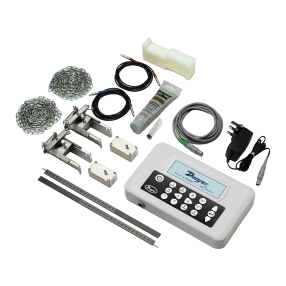
1: General Description Supplied Hardware The PUB equipment is supplied in a rugged polypropylene carrying case fitted with a foam insert to give added protection for transportation. The supplied components are shown in Figure 1.2. Transducer Cables (x2) Test Block Chains (x2) Ultrasonic Couplant 4 to 20 mA /... -
Page 8: Pub Instrument
1: General Description PUB Instrument The PUB is a microprocessor controlled instrument operated through a menu system using an inbuilt LCD display and keypad. It can be used to display the instantaneous fluid flow rate or velocity, together with totalized values. The instrument can also provide a variable current or variable ‘pulse’... -
Page 9: Keypad
1: General Description Numerical keypad Scroll RIGHT Scroll LEFT with dual function keys ON/OFF Scroll UP ENTER (SELECT) Scroll DOWN Figure 1.4 Keypad 1.4.2 Keypad The instrument is configured and controlled via a 16-key tactile membrane keypad, as shown in Figure 1.4. ON/OFF Key The ON/OFF key is shown on the top left of the keypad. -
Page 10: Power Supply And Battery Charging
1: General Description 1.4.3 Power supply and battery charging Operating power is provided by an internal battery that can be charged from the utility supply using the supplied external charger. When you first receive the unit you must put the battery on charge for a minimum of 6.5hrs before use. -
Page 11: 2: Installation
2: Installation 2: Installation Transducer Positioning In many applications an even flow velocity profile over The PUB equipment expects a uniform flow profile as a a full 360° is unattainable due, for example, to the distorted flow will produce unpredictable measurement presence of air turbulence at the top of the flow and errors. -
Page 12: Transducer Attachment
2: Installation Transducer Attachment The transducers are fitted to adjustable transducer holders which are secured to the pipe using wrap-around chains and mechanically connected together by a steel separation bar. The separation bar also acts as a ruler to allow the distance between the transducers to be accurately set to the value determined by the PUB instrument. When fitting the transducer holders, it is easiest to assemble them onto the separation bar and adjust to the required separation distance before attaching them to the pipe. -
Page 13: Fitting The Transducers
2: Installation On each transducer holder, attach one end of a securing chain to a hook on the tensioning bar (B), wrap the chain (G) around the pipe and then attach it to the hook on the other end of the tensioning bar while keeping the chain as tight as possible. -
Page 14: 3: Operating Procedures
3: Operating Procedures 3: Operating Procedures Initial instrument setup (Paragraph 3.1) Battery charging, Set date/time, Language, Backlight Connect and take basic flow readings At a one-off location At a frequent location Manage site details (Paragraph 3.2) (Paragraph 3.3) (Paragraph 3.4) QUICK START VIEW EDIT SITE DATA Set up a named site... -
Page 15: Setting-Up The Instrument
3: Operating Procedures Setting-up the Instrument 3.1.1 Using the instrument for the first time Before you use your PUB for the first time you should first charge the battery, then select the display language and set-up the internal clock, as described below. Charging the battery Connect the external battery charger to the charger socket at the bottom of the instrument then switch on the utility supply. -
Page 16: Enabling/Disabling The Backlight
3: Operating Procedures Setting the Date & Time SETUP INSTRUMENT DD-MM-YY HH:MM:SS Select Setup Instrument from the MAIN Qxx.xx% MENU. The screen shown here should be Set Date & Time : dd-mm-yy hh:mm:ss displayed. Calibrate 4-20mA Select Set Date & Time and press the ENTER Pulse status Backlight Disabled... -
Page 17: Using The Quick Start Menu
3: Operating Procedures Using the Quick Start Menu If you want to perform a ‘one-time’ flow reading at a particular pipe location, the Quick Start menu provides the quickest way to set up the PUB system and access the FLOW READING screen. If the point at which you intend to take the measurement is likely to require regular monitoring, it is best to set it up as a ‘Site’... - Page 18 3: Operating Procedures PIPE WALL MATERIAL DD-MM-YY HH:MM:SS Select the pipe wall material from the list provided, then press the ENTER key. Select pipe wall material If the material is not listed select Other and Mild Steel enter the propagation rate of the pipe wall S' less Steel 316 material in meters/sec.
- Page 19 3: Operating Procedures 15. The SENSOR SEPARATION screen now displays SENSOR SEPARATION DD-MM-YY HH:MM:SS Site : Quickstart a summary of the entered parameters and Pipe : 0.40 Inches informs you of the mode of operation and the Wall : 0.20 Inches distance to set up between the sensors.
-
Page 20: Using The System At A Regularly Monitored Location
3: Operating Procedures Flow monitoring The FLOW READING screen is the one most used during normal monitoring operation. It shows the instantaneous fluid flow together with totalized values (when enabled). In this mode you can select the flow measurement units by pressing keys 7 (liters), 8 (Gallons, Barrels) or 9 (m³), or change the display to show velocity by pressing key 4. - Page 21 3: Operating Procedures 11. The SENSOR SEPARATION screen now displays SENSOR SEPARATION DD-MM-YY HH:MM:SS Site : MySite a summary of the entered parameters and Pipe : 4.00 Inches informs you of the type of sensor to be used, the Wall : 0.20 mode of operation, and the distance to set up Sensors...
-
Page 22: Managing Named Sites
3: Operating Procedures Managing Named Sites If you want to monitor a particular site location frequently you can set up a named ‘Site’ to store the installation details, such as pipe dimensions and material, required to set-up the PUB system. These can then be recalled later when revisiting that particular location. -
Page 23: Changing A Site Name
3: Operating Procedures 3.4.2 Changing a site name To change a site name, use the same method described above for generating a new site: but in this case select a current site name to change rather than an EmptySite. Instrument Calibration The PUB is fully calibrated before it leaves the factory;... -
Page 24: Adjusting The Calibration Factor
3: Operating Procedures Press the Options key to access the FLOW FLOW READING OPTION DD-MM-YY HH:MM:SS READING OPTION screen shown. Data review Select Set zero flow (m/s) and press the Zero Cutoff (m/s) 0.00 ENTER key. Set zero flow (m/s) 0.00 Damping (secs) Press the ENTER key on the subsequent screen... -
Page 25: Adjusting The Roughness Factor
3: Operating Procedures 4. Press the Options key to access the FLOW FLOW READING OPTION DD-MM-YY HH:MM:SS READING OPTION screen shown. Data review 5. Scroll down and select Calibration factor. Zero Cutoff (m/s) 0.00 Set zero flow (m/s) 0.00 6. Change the calibration factor according to the Damping (secs) error calculated in step 3. -
Page 26: Adjusting The Damping Factor
3: Operating Procedures With the system running in FLOW READING mode: FLOW READING OPTION DD-MM-YY HH:MM:SS Press the Options key to access the FLOW READING OPTION screen shown. Data review Scroll down and select Roughness factor. Zero Cutoff (m/s) 0.00 Set zero flow (m/s) 0.00 Change the roughness factor according to the... -
Page 27: Performing Monitoring Functions
3: Operating Procedures Performing Monitoring Functions 3.6.1 How to measure totalized flows (manually) The basic measurement indicated on the FLOW READING screen is the instantaneous flow rate, which in some applications may vary over a period of time. Average flow rates are therefore often required in order to get a better understanding of an application’s true performance. -
Page 28: How To Stop The Totalizer Temporarily
3: Operating Procedures 3.6.2 How to stop the totalizer temporarily If you want to stop the totalizer temporarily for operational reasons, set the Totalizer option to Stall in the FLOW READING OPTIONS screen as described above. This will stop the totalizer operation without affecting its current values. - Page 29 3: Operating Procedures Signal calibration SETUP INSTRUMENT DD-MM-YY HH:MM:SS Select Setup Instrument from the MAIN Qxx.xx% MENU, to access the SETUP INSTRUMENT Set Date & Time : dd-mm-yy hh:mm:ss screen. Calibrate 4-20mA Select Calibrate 4-20mA. Pulse output Backlight Disabled Factory settings Change Language Exit CALIBRATE 4mA...
-
Page 30: Pulse Output
3: Operating Procedures Convert the measured current to flow rate Assume the maximum flow rate is F (gal/min) and the minimum flow rate F is ‘0’ (gal/min), as shown. [0-16 mA scale] [0-20 mA scale] [4-20 mA scale] I (mA) To calculate the flow rate (gal/min) for a measured current I(mA) then: 0-20 mA 0-16 mA... - Page 31 3: Operating Procedures Note: This does not apply if the PULSE OUTPUT menu is accessed by pressing the Pulse key when operating in the FLOW READING mode. Calibrating the pulse output signal range (volumetric mode) PULSE OUTPUT DD-MM-YY HH:MM:SS With the instrument operating in the FLOW Pulse output is ON Qxx.xx% READING mode, press the Pulse function key to...
- Page 32 3: Operating Procedures Calibrating the pulse frequency range PULSE OUTPUT DD-MM-YY HH:MM:SS With the instrument operating in the FLOW A1 Pulse Frequency is ON Qxx.xx% READING mode, press the Pulse function key Flow units to access the PULSE OUTPUT screen. Output Frequency Select Max Pulse Freq (Hz) and enter the...
-
Page 33: 4: Maintenance & Repair
4: Maintenance & Repair 4: Maintenance & Repair This instrument does not contain any user-serviceable parts. The following notes are provided as a guide to general equipment care Do not disassemble this unit unless advised by Dwyer. Return the unit to an approved service agent or place of purchase for further advice. -
Page 34: 5: Troubleshooting
5: Troubleshooting 5: Troubleshooting Overview If you have a problem with your flow monitoring system it can be due to any of the following: Faulty instrument If you suspect the instrument is faulty, you can check it out using a test block as described in Paragraph 5.4. This will establish that the instrument is functional and receiving a healthy signal from the connected transducers. -
Page 35: General Troubleshooting Procedure
5: Troubleshooting Automatic signal loss recovery If the signal is lost or the Quality falls below 40%, the set up procedure, which is normally invoked by selecting Read Flow in the main menu, is automatically run until a good quality signal is found. General Troubleshooting Procedure START Recharge the battery. -
Page 36: Warning & Status Messages
5: Troubleshooting Warning & Status Messages FLOW RATE ERRORS No flow signal Interpretation: This message appears when the transducers cannot send or receive signals to each other. Response: Check that all cables are connected, transducers are on the pipe correctly with sufficient couplant on the face. - Page 37 5: Troubleshooting 4-20mA ERRORS mA out > Max Interpretation: The actual flow is higher than the maximum set on the mA range. Response: Re-scale the 4 to 20 mA output to be able to cope with the higher flow – see page 24.
-
Page 38: Test Block
5: Troubleshooting Sensors: INVALID Interpretation: The selected temperature is higher than the maximum allowed for the sensor type. Response: Enter a different temperature. Mode: Err Typ Interpretation: The selected sensors are invalid and the mode cannot be verified. Response: Select a mode that gives a non-zero separation distance. BATTERY ERRORS Battery Low Interpretation: The battery has discharged to below 30% remaining. -
Page 39: Microprocessor Reset Facility
5: Troubleshooting Select Sensor mode and position the cursor at Diagonal and press ENTER to return to the SENSOR SELECTION menu. Select Exit and press ENTER to return to the SENSOR SEPARATION screen. Check that the parameters displayed are correct. Apply acoustic couplant to the sensors and attach them to the test block with the connectors positioned towards the center of the test block as shown, and temporarily secure them in place using elastic bands or tape. - Page 40 5: Troubleshooting Gain Gain values are typically in the range 600 to 850. Switches Typical Switches values are None and *10. On small pipes (and when using the test block) the value should be None. A Switch value of *100 indicates poor sensor set-up or poor connections. UP/DN time difference The difference in transit times between the upstream and downstream signals due to the fluid flow.
-
Page 41: 6: Specification
6: Specification 6: Specification GENERAL DSP Measurement Technique: Transit time. Timing Resolution: 50 pico-seconds, continuous signal level indication on display. Flow Velocity Range: Minimum Velocity 0.33 ft/s; Max Velocity 65.6 ft/s: Bi-directional. Turn Down Ratio: 100:1 Accuracy: ±0.5% to ±2% of flow reading for flow rate >0.66 ft/s and Pipe ID >3.0 inches (75 mm). ±3% of flow reading for flow rate >0.66 ft/s and Pipe ID in range 0.5 to 3.0 inches (13 to 75 mm). - Page 42 6: Specification TRANSDUCER SETS Standard transducers: Temperature Range -4°F to +275°F (-20°C to +135°C). 'PUB-A' (standard) 0.5 to inch (13 to 115 mm) pipe OD (2 MHz). 'PUB-B' (standard) 2 to 79 inch (50 to 2000 mm) pipe OD (1 MHz). LANGUAGES Standard Supported Languages: English, French, German, Italian, Spanish, Portuguese, Russian, Norwegian, Dutch, Swedish.
- Page 43 6: Specification MECHANICAL Carrying case: Rating: All components are contained in a hard-wearing polypropylene carrying case with a protective moulded foam insert. Enclosure: Material: Flame retardant injection moulded ABS. Dimensions: 10.4 x 6.6 x 2.0 inches. Weight (Including Battery): 2.4 lb. Protection: IP54.
- Page 44 6: Specification ©Copyright 2012 Dwyer Instruments, Inc. Printed in USA 9/12 DWYER INSTRUMENTS, INC. Phone: 219/879-8000 www.dwyer-inst.com P.O. BOX 373 • MICHIGAN CITY, INDIANA 46360, USA Fax: 219/872-9057 email: info@dwyer-inst.com...
Need help?
Do you have a question about the PUB Series and is the answer not in the manual?
Questions and answers