
Summary of Contents for GE Measurement Sentinel LCT4
- Page 1 Measurement & Control Flow Sentinel™ LCT4 User’s Manual 910-297 Rev. A February 2014...
- Page 3 Sentinel™ LCT4 Ultrasonic Flow Meter for Liquid Custody Transfer Measurement User’s Manual 910-297 Rev. A February 2014 www.ge-mcs.com ©2014 General Electric Company. All rights reserved. Technical content subject to change without notice.
- Page 4 [no content intended for this page]...
- Page 5 Preface Information and Safety Paragraphs Note: These paragraphs provide information that provides a deeper understanding of the situation, but is not essential to the proper completion of the instructions. IMPORTANT: These paragraphs provide information that emphasizes instructions that are essential to proper setup of the equipment.
- Page 6 Environmental Compliance Waste Electrical and Electronic Equipment (WEEE) Directive GE Measurement & Control is an active participant in Europe’s Waste Electrical and Electronic Equipment (WEEE) take-back initiative, directive 2012/19/EU. The equipment that you bought has required the extraction and use of natural resources for its production. It may contain hazardous substances that could impact health and the environment.
-
Page 7: Table Of Contents
Contents Chapter 1. Features and Capabilities 1.1 Overview....................1 1.1.1 Applications . - Page 8 Unlocking the Sentinel LCT4 ........
- Page 9 Contents 3.7.1 Entering Fluid Type ................67 3.7.2 Entering Signal Parameters.
- Page 10 Updating Sentinel LCT4 Instrument Software ........
- Page 11 Contents 7.2.9 E13: Settle Tracking AGC..............119 7.2.10 E14: Tracking Seek Mode .
- Page 12 Contents [no content intended for this page] Sentinel™ LCT4 User’s Manual...
-
Page 13: Chapter 1. Features And Capabilities
1.1.1 Applications The Sentinel LCT4 is designed specifically for the custody transfer of petroleum liquids, meeting the strict requirements of API MPMS 5.8, OIML R117-1 and MID MI-005. •... -
Page 14: Meter Components
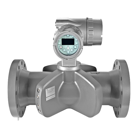
Chapter 1. Features and Capabilities 1.1.3 Meter Components Figure 16 on page 34 shows the complete Sentinel LCT4 system and each of the items is described in Table 1 below. Table 1: Sentinel LCT4 System Components Component Description Meter Body... - Page 15 Chapter 1. Features and Capabilities 1.1.3 Meter Components (cont.) Figure 1: Sentinel LCT4 Ultrasonic Flow Transmitter Assembly (3” to 24” Diameter Pipes) Note: Actual design changes slightly with size. Sentinel™ LCT4 User’s Manual...
-
Page 16: Marking And Labeling
Tag Plates There are four tag plates affixed to the Sentinel LCT4 which provide details about the system. Three are located on the vessel and one is located on the transmitter. Their locations are shown in the Figure 2 below. - Page 17 Chapter 1. Features and Capabilities 1.1.4c Model Number String SEN - LCT4 - B - C - D - E - F - G - H - I - J - K - L - Z B - CONFIG 4-path full bore - F C - SIZE 3”...
- Page 18 Chapter 1. Features and Capabilities 1.1.4d Specification Tag Plate The Specification Tag Plate (see Figure 4 below) contains information pertaining to the build and test of the pressure vessel. It contains OIML certificate information, in addition to the the following information: •...
-
Page 19: Theory Of Operation
They perform the actual data transmission and collection, thus interrogating the flow. The transducers in the Sentinel LCT4 Measurement System were specifically designed to be replaced under normal operating conditions. In the event that a transducer becomes damaged or non-functional, it can be replaced without shutting down the pipeline. -
Page 20: Multipath Design
For this reason, the factory has tested the Sentinel LCT4 under various conditions in an effort to determine its operational limits. Flow conditioning is optional but highly recommended under certain installation conditions. -
Page 21: Maximum And Minimum Flow
1.2.5 Maximum and Minimum Flow Maximum and minimum flow rates through the Sentinel LCT4 Ultrasonic Liquid Flow Transmitter are based on the pipe diameter and the process fluid pressure. The information in Table 3 below is approximate, and is based on representative liquid components at a process temperature of 70°F (21°C). -
Page 22: Specifications
The system specifications for the Sentinel LCT4 Ultrasonic Liquid Flow Transmitter are divided into the following categories: 1.3.1 Operation and Performance Note: The Sentinel LCT4 has been designed to meet the OIML R117-1, MID MI-005 and API MPMS 5.8 requirements. 1.3.1a Fluid Types Liquid hydrocarbons, crude and refined products, other liquids. -
Page 23: Meter Body
Stainless steel SA351 Gr. CF8 • Stainless steel SA351 Gr. CF8M Others on request. 1.3.2c Flowcells 3” (75 mm) to 24” (600 mm) Others on request. SECTION B-B Figure 8: Flowcell Assembly for Sentinel LCT4 with 3” and 4” Pipes Sentinel™ LCT4 User’s Manual... - Page 24 Flowcells (cont.) Section B-B1 Figure 9: Flowcell Assembly for Sentinel LCT4 with 6” to 24” Pipes Note: Use Figure 8 on page 11 and Figure 9 above to identify L, H2 and A measurements in Table 4 on page 13. The A dimension is the MAX depth of the system.
- Page 25 Chapter 1. Features and Capabilities 1.3.2c Flowcells (cont.) Table 4: Flowcell Dimensions Dimensions in English Units Dimensions in Metric Units Pipe Diameter Flange Class (rounded) (rounded) (inches) (lb) L (in.) H2 (in.) A (in.) L (mm) H2 (mm) A (mm) 150# 13.82 300#...
- Page 26 Chapter 1. Features and Capabilities 1.3.2d Flange Ratings • 150 # • 300 # • 600# Others on request. 1.3.2e Pipe Schedules • • • • • Others on request. 1.3.2f PED Compliance • PED Cat II, Module B + C1 1.3.2g Installation Requirement The meter must be installed with 20D straight piping upstream and 5D straight piping downstream.
-
Page 27: Electronics
Chapter 1. Features and Capabilities 1.3.3 Electronics 1.3.3a Electronics Enclosure Material Epoxy-coated aluminum Stainless steel A351, Gr 316/316L (optional) 1.3.3b Weight 29 lb (13.2 kg) aluminum 58 lb (24.3 kg) stainless 1.3.3c Dimensions Size (l x h x d): 13” x 11” x 9” 1.3.3d Ingress Protection Type 4X / IP66... -
Page 28: Custody Transfer Approvals
Chapter 1. Features and Capabilities 1.3.3j Digital Interfaces • HART over 4/20 mA output (version 6) • PanaLink over RS232/485/USB • Modbus over RS232/485 (optional) 1.3.3k Flow Computer Functionality Integrated flow computer with full P and T volume corrections according to API 11.1 1.3.3l Hazardous Area Classification •... -
Page 29: Standards
Chapter 1. Features and Capabilities 1.3.5 Standards The Sentinel LCT4 has been designed in accordance with the following standards: • ASME B31.3 • ASME Section IX • ASME B16.5 • ANSI/NACE MR0175/ISO 15156 AND NACE MR0103 • ANSI/NACE B.1.20.1 •... -
Page 30: Weight
Chapter 1. Features and Capabilities 1.4.3 Weight Table 6 below lists the worst case dry weights for each vessel size by pressure class. The weights are based on the heaviest standard material provided, in this case, stainless steel. These weights include the transmitter supplied with a stainless steel enclosure. -
Page 31: Flowrates
Chapter 1. Features and Capabilities 1.4.4 Flowrates Table 7 below includes OIML approved minimum and maximum flowrates for which the system has been shown to maintain OIML accuracies and repeatabilities. Table 7: OIML Approved Flowrates OIML Maximum/Minimum Flow Rates English [GPM] Metric [m /hr] Nominal Vessel... -
Page 32: Loads And Forces
Startup The Sentinel LCT4 does not have any specific startup requirements once it has been fastened into the piping system. Power should be supplied in accordance with local and national electrical codes. The line does not need to be full of fluid for the system to be powered on. -
Page 33: Certification
Chapter 1. Features and Capabilities 1.5 Certification 1.5.1 Pressure Equipment Directive (PED) Marking Information - TBD 1.5.2 Canadian Registration Number (CRN) CRN No: 0F15659 (all provinces) Sizes: 3", 4", 6, 8" Pressure Classes: #150, #300, #600 Material: SA216 WCB, SA352 LCB, SA351 CF8, SA351 CF8M 1.5.3 Custody Transfer Performance Approvals 1.5.3a Standard... -
Page 34: List Of Reference Drawings And Documentation
712-1827 Outline & Installation, SEN898 Enclosure, Aluminum, Local Mount 712-1828 Outline & Installation, SEN898 Enclosure, SS316, Local Mount 712-1832 Outline & Installation, Sentinel LCT4, Local Mount 712-1833 Outline & Installation, Sentinel LCT4, Remote Mount 1.6.3 Manuals 910-297 Sentinel LCT4 User's Manual (this manual) -
Page 35: Disclaimer
Chapter 1. Features and Capabilities 1.7 Disclaimer The warranties set forth herein are exclusive and are in lieu of all other warranties whether statutory, express or implied (including warranties of merchantability and fitness for a particular purpose, and warranties arising from course of dealing or usage or trade). - Page 36 Chapter 1. Features and Capabilities [no content intended for this page] Sentinel™ LCT4 User’s Manual...
-
Page 37: Chapter 2. Installation
This section provides general information with respect to the mechanical and electrical installation, and should be thoroughly reviewed before the system is installed. To ensure safe and reliable operation of the Sentinel LCT4, the system must be installed in accordance with the guidelines established by GE Sensing, as explained in this chapter. -
Page 38: Unpacking
2.3 Unpacking The Sentinel LCT4 will typically be packaged in a wooden crate, the size of which will depend on the size of product ordered. There Sentinel LCT4 will be secured by several 2x4 wood blocks to prevent shifting during transit. Simply remove these 2x4 braces to unpack the system. -
Page 39: Mechanical Installation
An additional length of straight pipe will help produce a more symmetrical flow profile, thus reducing the measurement uncertainty. 3D min Upstream Upstream Figure 10: Typical Sentinel LCT4 Installation, Uni-Directional Flow Sentinel™ LCT4 User’s Manual... - Page 40 Chapter 2. Installation 2.5 Mechanical Installation (cont.) Bi-Directional 20 D Temp. and Pressure transmitters should b located elsewhere for bi-directional installations. Figure 11: Typical Sentinel LCT4 Installation, Bi-Directional Flow Sentinel™ LCT4 User’s Manual...
-
Page 41: Installation Precautions
Make sure the gasket is centered on the flange faces and does not protrude into the pipe, as protrusion of the gasket into the pipe may cause flow profile disturbances. • Make sure the Sentinel LCT4 is oriented with the flow transmitter in a vertical position at the top, as shown in Figure 12 below. Figure 12: Lifting Strap Locations... -
Page 42: Lifting Instructions
Use proper lifting techniques when moving the Sentinel LCT4 (see Figure 13 below). No lifting hooks or eyelets are provided. The recommended method for lifting the Sentinel LCT4 is by using lifting straps on each side of the pressure vessel with a stabilizer bar between them, located above the transmitter head. Additional care may need to be taken to prevent the transmitter from rotating, especially on the smaller systems where the transmitter weight is a larger percentage of the total system weight. -
Page 43: Installing The System
2.6.1a Installation Location Proper installation of the Sentinel LCT4 is important to achieve maximum performance from the system. The following installation recommendations provide general guidelines of how this system should be installed. If the following recommendations cannot be met, please consult the factory for a more detailed review of the application to see what performance may be achievable. - Page 44 In general, the best practice is to calibrate as much of the measuring section as possible. This would include conditioning plates, upstream and downstream straight run and the Sentinel LCT4. While this is not always possible or cost effective this will provide the best transferability from calibration to field usage. This methodology is highly recommended for Custody Transfer Master Meter and Duty systems to maintain the lowest possible system uncertainty.
-
Page 45: Guidelines For Installing Pipe Insulation
Chapter 2. Installation 2.6.1g Fluid Comments - To avoid measurement errors suitable measures should be taken make sure the line is full and gas in the line is kept below 1%. While the system may still be able to measure with larger amounts, it has the potential to affect accuracy. -
Page 46: Making Electrical Connections
2 Analog Inputs (4-20 mA) + 1 RTD Input Corrected Flow Volumetric Computer RS232/RS485 Modbus Flow Power RS232 Pressure Temperature RS485 Sentinel LCT4 PanaView™ SEN898 Meter Calibration, Data Collection, Instrument Interface Configuration, and Security Software Figure 16: Sentinel LCT4 Flow Measurement System Connections Sentinel™ LCT4 User’s Manual... -
Page 47: Removing The Covers
Chapter 2. Installation 2.7.1 Removing the Covers WARNING! Always disconnect the line power from the meter before removing either the front display cover or the wiring access cover. This is especially important in a hazardous environment. 1. Disconnect any previously wired power line from the flow transmitter. 2. -
Page 48: Cable Tie-Down Posts
2.7.2 Cable Tie-Down Posts There are two cable tie-down posts provided in the Sentinel LCT4 (see Figure 18 below). These posts enable the user to insert a cable tie through them, and secure the wiring coming into or out of the instrument. The posts rotate on the printed circuit board to provide ease-of-use. -
Page 49: Wiring The Line Power
2.7.3 Wiring the Line Power The Sentinel LCT4 may be ordered for operation with a power input of 100-240 VAC or 12–32 VDC. The label on the side of the electronics enclosure lists the required line voltage and power rating. The fuse size is listed in “Specifications”... - Page 50 Chapter 2. Installation 2.7.3 Wiring the Line Power (cont.) Note: All wires shall have a temperature/type rating 10K above the maximum service temperature of 85°C, be stripped back 5/16 in. (8 mm) and torqued to a minimum of 4.4 in. lb. (0.5 Nm). 3.
-
Page 51: Wiring The Serial Port
4. If the wiring of the unit has been completed, reinstall the wiring access cover and tighten the set screw. 2.7.5 Wiring the Modbus Communications Line (Optional) The Sentinel LCT4 uses the RS485 interface with Modbus communications protocol for a maximum line distance up to 4000 ft (1200 m). GE recommends using shielded 18-24 AWG (0.82 - 0.2 mm )) cable having a characteristic impedance of 120 ohms, with 120-ohm termination at each end of the communications line. -
Page 52: Wiring The Alarm Relay
Chapter 2. Installation 2.7.6 Wiring the Alarm Relay Note: The alarm relay can be wired as either Normally Open (NO) or Normally Closed (NC). An alarm relay should be wired for fail-safe operation. In fail-safe mode, the alarm relay is constantly energized, except when it is triggered, or a power failure or other interruption occurs. -
Page 53: Wiring The 4-20Ma Analog Input (Optional)
The inputs may be used to process temperature, density and pressure signals. Note: To enter programming data during operation of the Sentinel LCT4, it will be necessary to know which input is assigned to which process parameter. This information should be entered in Appendix C, Data Records. - Page 54 Chapter 2. Installation 2.7.7 Wiring the 4-20mA Analog Input (cont.) With External Power Supply 24 VDC POWER SUPPLY – Transmitter Analog Input Sensor + IN Ain RTN – OUT +24V With Internal Power Supply Analog Input Transmitter Ain RTN Sensor –...
- Page 55 AIN1 AIN3 AIN2 AIN1 Analog Input 1 Analog Input 2 Analog Input 3 Figure 26: Terminal Locations for 3 Analog Input Option Powered – Sentinel LCT4 provides +24VDC – Transmitter for the Transmitter AIN3 AIN2 AIN1 AIN3 AIN2 AIN1 *You can wire to either RTN1 TB connection.
- Page 56 Chapter 2. Installation 2.7.7 Wiring the 4-20mA Analog Input (cont.) RTD1 AIN2 AIN1 RTD1 AIN2 AIN1 RTD1 AIN2 AIN1 Analog Input 1 Analog Input 2 RTD Input 3 Figure 28: Terminal Locations for 2 Analog Input and 1 RTD Input Option 4-Wire RTD 3-Wire RTD Current...
-
Page 57: Wiring The Frequency/Totalizer Output
The use of 12-24 AWG (3.3 - 0.2 mm ) is recommended for single conductor wiring, and 16-24 AWG (1.5 - 0.2 mm ) is recommended for two conductors per terminal. Frequency/Totalizer Output (Open Drain) Sentinel LCT4 Counter Volts + (Int. Pwr. Sup.) Load Volts -... -
Page 58: Wiring The 4-20 Ma Analog Output
Chapter 2. Installation 2.7.9 Wiring the 4-20 mA Analog Output The standard configuration of the flow transmitter includes an isolated 4-20 mA analog output. Connections to this output may be made with standard 12-24 AWG (3.3 - 0.2 mm ) twisted-pair wire for a single conductor, and 16-24 AWG (1.5 - 0.2 mm ) wire for a two-conductor connection, but the current loop impedance for these circuits must not exceed 1000 ohms. - Page 59 5. If wiring of the unit has been completed, reinstall the wiring access cover on the enclosure and tighten the set screw. After the Sentinel LCT4 has been completely installed and wired, proceed to Chapter 3, Operation, to program the flowmeter.
- Page 60 Chapter 2. Installation [no content intended for this page] Sentinel™ LCT4 User’s Manual...
- Page 61 Chapter 2. Installation Front Display Wiring Access Cover Sentinel™ LCT4 User’s Manual...
- Page 62 Chapter 2. Installation ALM2 RJ45 ALM1 Ain3 Ain2 Ain1 Sentinel™ LCT4 User’s Manual...
- Page 63 Chapter 2. Installation (3) 3/4" NPT CABLE GLANDS PORTS (CABLE ENTRY ON OPPOSITE SIDE OF ENCLOSURE) MODBUS / TCP CONNECTOR (NON-IS ONLY) (2) CABLE TIE DOWN POINTS GROUNDING SCREWS FOR 2-WIRE SHIELD CABLES (RECOMMENDED) 8-32 SCREW MODBUS NETWORK RS232/485 POWER CORD TERMINAL MODBUS (TRANSMIT / DATA -) DC OPTION: AC OPTION:...
- Page 64 Chapter 2. Installation FLOW CELL (REAR VIEW) FLOW INTERNAL CABLE W/FEEDTHRU, SEN898 ELECTRONICS 4-WIRE INTERNAL CABLE, SINGLE, 4X FEEDTHRU PORT PORT FLOW CELL (TOP VIEW) PORT PORT ENCLOSURE FLOW PCB (VIEWED FROM TOP) (VIEWED FROM BOTTOM) INTERNAL CABLE, SINGLE, 4X INTERNAL CABLE W/FEEDTHRU, 4-WIRE DUAL PLANE (3”...
- Page 65 Chapter 2. Installation FLOW CELL (REAR VIEW) FLOW INTERNAL CABLE W/FEEDTHRU, SEN898 ELECTRONICS 4-WIRE INTERNAL CABLE, SINGLE, 4X FEEDTHRU PORT FLOW CELL (TOP VIEW) PORT ENCLOSURE FLOW PCB (VIEWED FROM TOP) (VIEWED FROM BOTTOM) INTERNAL CABLE, SINGLE, 4X INTERNAL CABLE W/FEEDTHRU, 4-WIRE SINGLE PLANE (6”...
- Page 66 Chapter 2. Installation FLOW CELL (REAR VIEW) FLOW SEN898 ELECTRONICS INTERNAL CABLE, 8-WIRE INTERNAL CABLE, SINGLE, 4X REMOTE CABLE PORT ENCLOSURE FLOW PCB (VIEWED FROM TOP) ENTRY PORT (VIEWED FROM BOTTOM) FLOW CELL W/ADAPTER PORT (TOP VIEW) PORT PORT INTERNAL CABLE, SINGLE, 4X DUAL PLANE (3”...
- Page 67 Chapter 2. Installation FLOW CELL (REAR VIEW) FLOW SEN898 ELECTRONICS INTERNAL CABLE, 8-WIRE INTERNAL CABLE, SINGLE, 4X REMOTE CABLE ENCLOSURE FLOW PCB ENTRY PORT (VIEWED FROM TOP) (VIEWED FROM BOTTOM) FLOW CELL W/ADAPTER (TOP VIEW) PORT PORT INTERNAL CABLE, SINGLE, 4X SINGLE PLANE (6”...
- Page 68 Chapter 2. Installation [no content intended for this page] Sentinel™ LCT4 User’s Manual...
-
Page 69: Chapter 3. General Programming
Chapter 3. General Programming Introduction The Sentinel LCT4 flow transmitter includes a User Program that provides access to the various programmable features of the instrument. This chapter describes step-by-step programming instructions using the internal keypad, shown in Figure 40 below. -
Page 70: Indicator Lights
Chapter 3. General Programming 3.2.1 Indicator Lights • If the Fault Indicator is lit, an instrument fault is detected. An error indication will be displayed in the lower right-hand corner of the Measurement View. • If the User Intervene Indicator is lit, an alarm has been triggered and will be kept latched until cleared by the user. -
Page 71: Program Menu Options
Unlocking and Locking To prevent unauthorized tampering with either the display or the user program, the Sentinel LCT4 has multiple security codes. After the security level has been set, one of these codes is required to change just the display (Display Lock), or the display and the user program (Full Lock). -
Page 72: Locking The Sentinel Lct4
2. Press , and proceed to step 4 below. [ENT] From the User Program: . The Sentinel LCT4 enters the User Program. 1. Press [ESC] 2. Press the [] key until USER is bracketed. 3. Press the [] key until Set Security is highlighted. Press [ENT] Sentinel™... - Page 73 [ESC] have chosen to fully lock the Sentinel LCT4, the screen appears similar to Figure 43 below, with a solid lock in the upper right corner. (For a meter with only the user program locked, the lock shows a keyhole in the center.) Figure 43: Screen with Locked Program Sentinel™...
-
Page 74: Setting Security
While following the programming instructions, refer to Figure 66 on page 136. Remember to record all programmed data in Appendix C, Data Records. To access the Status submenu: . The Sentinel LCT4 enters the User Program. 1. Press [ESC] 2. -
Page 75: Entering Fluid Data (Not Supported At This Time)
(once to enter and again to confirm the selection). [ENT] To access the Fluid submenu: 1. Press . The Sentinel LCT4 enters the User Program. [ESC] 2. Press the [] key until is bracketed in the top left corner and press PROG [ENT]. - Page 76 If Off is chosen, no further choices are available. • If Single is chosen, the Sentinel LCT4 will select and automatically display the Kinematic Viscosity. To change the value, press Use the arrow keys to change the value (available in document #914-004, Soundspeeds [ENT].
-
Page 77: Entering Signal Parameters
4. Scroll to the Signal option and press [ENT]. 5. The prompt requests the Zero Cutoff. Near “zero” flow, the Sentinel LCT4 may have fluctuating readings due to small offsets (caused by factors such as thermal drift in the fluid). The zero cutoff causes velocity measurements less than the cutoff to be reported as zero. - Page 78 4. Scroll to the Error Limits option and press [ENT]. 5. The first prompt requests the Min Signal limit for the transducer signal received by the Sentinel LCT4. The E1:LOW SIGNAL error message appears if the signal strength falls below the limit programmed here. Press Use the arrow keys to change the value and press [ENT].
-
Page 79: Composite Programming
[ENT]. • If Other was selected, the Sentinel LCT4 requests the fluid soundspeed (for Normal fluids) or minimum and maximum soundspeed (for Tracking Window fluids). In either case, scroll to the Soundspeed option and press Use the arrow keys to enter the appropriate soundspeed, and press [ENT]. -
Page 80: Entering Signal Parameters
(once to enter and again to confirm the selection). [ENT] To enter the Signal submenu: . The Sentinel LCT4 enters the User Program. 1. Press [ESC] 2. Press the [] key until PROG is bracketed and press [ENT]. -
Page 81: Setting Up Input Data Feeds
Chapter 3. General Programming 3.7.3 Setting Up Input Data Feeds In the Inputs submenu, set the status for three types of inputs: • Temperature • Pressure • Density To set up the desired inputs, complete the following steps: 1. From the COMPOSITE menu, select Inputs, and press [ENT]. The next screen lists three types of inputs: Temperature, Pressure, and Density. - Page 82 Chapter 3. General Programming 3.7.4b API Conditions 1. Select API Conditions. Press [ENT]. The next screen displays two options: Base Condition and Flow Measure At... 2. Select Base Condition and press [ENT]. The next screen displays four options: 60°, 20°, 15° and User Defined...
-
Page 83: Configuration
Chapter 3. General Programming Configuration To configure your Sentinel meter, proceed as follows: 1. From the main menu, use the right arrow key to scroll to CONFIG. There are five options: Units, Communication, Reset Totals, Totalizer Errors and Date/Time. Use the arrow keys to select an option to be configured. -
Page 84: Inputs/Outputs
Refer to Figure 69 on page 139 or Figure 70 on page 140. To enter the IO Menu, proceed as follows: 1. Press [ESC]. The Sentinel LCT4 enters the User Program. 2. Press the [>] key until IO is bracketed and press [ENT]. -
Page 85: Analog Output
Chapter 3. General Programming 3.9.1 Analog Output To program an analog output, proceed as follows: 1. Select Analog Output to bring you to the menu. 2. Select Status. Select Off to disable output or On to enable output. 3. Select the Channel of the data source you want to output. 4. - Page 86 Chapter 3. General Programming 3.9.2a Frequency Output To program a Frequency output, proceed as follows: 1. Units - Choose the channel, parameter and units to output. 2. Fbase - Enter the lowest value of the Frequency range you want to output. 3.
-
Page 87: Alarms
Chapter 3. General Programming 3.9.3 Alarms To program an alarm output, proceed as follows: 1. Select Status, and choose either OFF, Normal, or Failsafe. a. OFF - Disables alarm functionality. b. Normal - Selection for conventional operation. c. Failsafe - Selection for fail-safe operation. 2. -
Page 88: Analog Inputs (Additional Option)
If a Calibration is not going to be performed, load nominal calibration values by selecting Reset Trim. This will enable 4-20 mA to be read with undetermined accuracy. However, to meet the Sentinel LCT4 accuracy specifications, a proper calibration must be performed as follows: •... -
Page 89: Rtd (Additional Option)
The Meter is set up to display 1C:RTD. e. Under IO/Slot 1/1C:Temp(RTD)/Mode choose temperature and enter in the right units. A 2 to 5 point calibration is allowed with Sentinel LCT4. • Cal points must be entered with the lowest temperature starting at setpoint #1, and in increasing order to the highest setpoint. -
Page 90: Display
Chapter 3. General Programming 3.10 Display To configure the display, proceed as follows: 1. From the main menu, use the arrow keys to scroll to DISP. The screen displays four options: Views, Contrast, Backlight, and Mode. Use the arrow keys to select an option to be configured. 2. -
Page 91: User Security
Chapter 3. General Programming 3.12 User Security From the main menu: 1. Use the arrow keys to scroll to USER. 2. The Edtcde screen displays three options: Edit Passcodes, Security, and Set Security. Select the desired option and press [ENT]. 3.12.1 Edit Passcodes This User option is made available only to Security Levels of User-Admin, Field Service, Factory and Engineering (see Table 12 on page 60). -
Page 92: Factory Status
Chapter 3. General Programming 3.13 Factory Status To access the Factory Status menu, proceed as follows: 1. From the main menu, use the arrow keys to scroll to FACTORY. The screen displays five options: Versions, Default Meter, Upgrade, System Info, and Tag. 2. -
Page 93: Chapter 4. Modbus Communications
Chapter 4. MODBUS Communications 4.1 Introduction The Sentinel LCT4 supports digital communications using the MODBUS/RTU protocol, with 2-wire RS-485 or 3-wire RS-232C as the physical layer. Data rate can be specified from 4800 to 19,200 bits per second (bps), with selectable parity, and number of stop bits (Default = 9600, Even, 1 Stop Bit) 4.2 Setting Up MODBUS Communications... - Page 94 Chapter 4. MODBUS Communications 4.2 Setting Up MODBUS Communications (cont.) 8. Total Units: To set the total units measurement, from the CONFIG menu select Total Units, and press [ENT]. Four options appear: M , Liters, Hectare-cm and Hectare-m. Use the arrow keys to select the appropriate measurement type, and press [ENT].
- Page 95 Chapter 4. MODBUS Communications Table 14: Modbus Register Map (cont.) Composite Channel 1 Channel 2 Channel 3 Channel 4 Register Register Register Register Register Category Measurement Type Size Format Address Address Address Address Address Signal UP +– Peak 2 LSW float 41 0x0028 1065 0x0428 2089 0x0828 3113 0x0C28 4137 0x1028 Processing DN +–...
- Page 96 Chapter 4. MODBUS Communications Table 14: Modbus Register Map (cont.) Composite Channel 1 Channel 2 Channel 3 Channel 4 Register Register Register Register Register Category Measurement Type Size Format Address Address Address Address Address Flow Totals FWD Energy 4 LSW double 145 0x0090 1169 0X0490 2193 0X0890 3217 0X0C90 4241 0X1090 REV Energy 4 LSW double 149 0x0094 1173 0X0494 2197 0X0894 3221 0X0C94 4245 0X1094 Totl.
- Page 97 Chapter 4. MODBUS Communications Table 14: Modbus Register Map (cont.) Composite Channel 1 Channel 2 Channel 3 Channel 4 Register Register Register Register Register Category Measurement Type Size Format Address Address Address Address Address Flow Totals REV Energy 2 LSW float 291 0x0122 1315 0x0522 2339 0x0922 3363 0x0D22 4387 0X1122 (scientific Register 2 notation)
- Page 98 Chapter 4. MODBUS Communications Table 14: Modbus Register Map (cont.) Composite Channel 1 Channel 2 Channel 3 Channel 4 Register Register Register Register Register Category Measurement Type Size Format Address Address Address Address Address Comm Parity 1 Unsigned 5123 Settings integer 0x1402 Stop Bits...
-
Page 99: Chapter 5. Hart Communications
Chapter 5. HART Communications Chapter 5. HART Communications Introduction The Sentinel LCT4 generates a 4-20 mA analog output signal that enables two-way communication with a HART communication device. Wiring the HART Interface Interconnect the HART interface and the HART device as shown in either Figure 46 or Figure 47 below. -
Page 100: Flowmeter Software Setup
Flowmeter Software Setup Sentinel LCT4’s require no special setup procedures by the user. The meter automatically configures itself for HART communication on startup. The analog output must be on, and the mode must be set to the desired state. See [I/O], analog output menu. -
Page 101: Host Interface
5.4.2a Analog Output The Sentinel LCT4 is equipped with a single 4-20 mA output (see Table 15 below for specifications), which can be configured using software to supply 24-volt power internally (active), or to regulate current from an external source (passive). - Page 102 Chapter 5. HART Communications Table 16: Device Variable Codes (cont.) Device Variable Code Device Variable Decimal (Hex) Measurement Classification Code Comp Ch. 1 Ch. 2 Ch. 3 Ch. 4 Code Classification 14 (0E) 62 (3E) 110 (6E) 158 (9E) 206 (CE) Not Classified CTPL 15 (0F)
- Page 103 For instance, if a Volumetric Flow variable unit is changed, all subsequent Volumetric Flow variables will switch to that unit. This keeps forward and reverse internal Sentinel LCT4 units in sync with the HART variable type. Table 17: Publishable Device Variables...
- Page 104 Chapter 5. HART Communications Table 17: Publishable Device Variables (cont.) Device Variable Code Device Variable Decimal (Hex) Classification Code Measurement Comp Ch. 1 Ch. 2 Ch. 3 Ch. 4 Code Classification Peak% 76 (4C) 124 (7C) 172 (AC) 220 (DC) Analytical UP Signal Q 77 (4D)
-
Page 105: Dynamic Variables
(PV, SV, TV and QV). Certain diagnostic variables have units specific to that diagnostic. Refer to the Sentinel LCT4 for details on the use of diagnostic variables indicated by the variable class specified as “Not Classified.”... -
Page 106: Additional Device Status
Table 18 below shows the error bits and associated SEN898 error condition. Table 18: Error Codes and Status Bits HART Additional Sentinel LCT4 Device Status Device Status Meaning Sentinel LCT4 Error Condition Class Bits Set Byte – – –... -
Page 107: Universal Commands
Chapter 5. HART Communications Universal Commands All universal commands are implemented per the HART Universal Command Specification (HCF_SPEC-127, rev. 6.0). The transducer serial number is not relevant to flowmeters, so a zero is returned in the first two data bytes of Command 14, Read Primary Variable Transducer Information. -
Page 108: Burst Mode Commands
Totals variable. Invalid selection is returned for non-totals variables. 5.9.2 Burst Mode Commands The Sentinel LCT4 does not support burst mode. 5.9.3 Catch Device Variable Command The Sentinel LCT4 does not support the catch device variable mechanism. Sentinel™ LCT4 User’s Manual... -
Page 109: Device-Specific Commands
Totals variable, it will clear all totals. Note: The function is global. Sentinel LCT4 can be configured to use individual transducer pairs, or channels, to measure flow in separate pipes. The clear totals command will reset the volume, mass, energy and time for every channel. -
Page 110: Tables
5.11.1 HART Engineering Units The unit types allowed for Sentinel LCT4 device variables in Error! Reference source not found, shown in Section Error! Reference source not found, are listed below. Unit types for device variables in Error! Reference source not found are shown, but only units from Publishable variables are listed. - Page 111 Chapter 5. HART Communications 5.11.1c Standard Volumetric Flow Table 23: Standard Volumetric Flow Class Variable Code Classification Unit Code Unit Description Volumetric Flow Standard cubic feet per hour Standard cubic feet per minute Standard cubic feet per second Standard cubic feet per day Standard cubic meters per day Standard cubic meters per hour Standard cubic meters per minute...
- Page 112 Chapter 5. HART Communications 5.11.1f Mass Flow Table 26: Mass Flow Class Variable Code Classification Unit Code Unit Description Mass Flow 5.11.1g Mass Table 27: Standard Volume Class Variable Code Classification Unit Code Unit Description Mass (FWD) Mass (REV) 5.11.1h Power Table 28: Power Class Variable...
-
Page 113: Performance
5.12.2 Power-Up The Sentinel LCT4 requires approximately 15 to 60 seconds to boot after it is energized, depending on whether the non-volatile memory is being restored from default. No HART requests are processed during initiation. The analog output will default to 4mA until the primary variable is available. -
Page 114: Command Response Delay
Long Messages The data field in Command 21, Read Unique Identifier Associated with Long Tag, is the largest that the Sentinel LCT4 will receive. The message contains 32 characters (bytes). The reply to Command 21 contains the largest data field sent by the Sentinel LCT4, 18 bytes (including the two status bytes). -
Page 115: Capability Checklist
Chapter 5. HART Communications 5.13 Capability Checklist Table 34: Capability Checklist Manufacturer, model and revision GE Measurement & Control Sentinel LCT4 flowmeter, Rev. 1.0 Device type Transmitter HART revision Device Description available 1 to 4 pairs of acoustic transducers, Number and type of sensors... -
Page 116: Default Configuration
Total lock Off (i.e., reset is enabled) Number of response preambles Refer to Chapter 3, Operation, for more information about factory default settings for the Sentinel LCT4. For DD or FDT/DTM files, consult GE. 5.15 Manufacturer and Device ID Table 36: Manufacturer and Device ID... -
Page 117: Chapter 6. Maintenance
1. To set up the RS232, connect one end of a 9-pin RS232 cable to the COM-1 serial port on a PC and the other end to Com Port I/O on terminal block TB2 on the Sentinel LCT4, as described in Chapter 2, Installation. - Page 118 [ENT] The Sentinel LCT4 screen should appear as in Figure 48 below after approximately one minute Power on the Sentinel LCT4, and enter ESC-R from the PC keyboard. The Sentinel LCT4 screen should appear as in Figure 48 below. Figure 48: Sentinel LCT4 Screen...
- Page 119 .cod extension. Double click on this file and click the Send button. The screens on the Sentinel LCT4 (Figure 50 below) and on Hyperterminal (Figure 51 below) should both display the status of the transfer.
- Page 120 5. To ensure the Sentinel LCT4 operates correctly, GE recommends defaulting the meter after software updates. From the Sentinel LCT4 Factory Menu, scroll to Default Meter and press [ENT]. Press the up arrow key [] and press [ENT] twice, or at power on, press and hold the [CLR-TOT] key until the following screen appears after several seconds.
-
Page 121: Checking The Meter Software
Chapter 6. Maintenance 6.1.2 Checking the Meter Software To check the meter software, complete the following steps: 1. Turn power on. The display should boot up with a typical cycling procedure. 2. To verify which version of software has been loaded: to enter the User Program. -
Page 122: Trimming 4-20 Ma Loop Using The Keypad
Chapter 6. Maintenance 6.1.3 Trimming 4-20 mA Loop Using the Keypad To trim the 4-20 mA loop using the keypad, complete the following steps: 1. In the User Program, scroll to with 4-20 Loop highlighted. Press [ENT]. 2. Scroll to Mode and press In the Mode window, scroll to Test[Trim] and press [ENT]. -
Page 123: Hardware Maintenance And Inspection
Chapter 6. Maintenance 6.2 Hardware Maintenance and Inspection WARNING! Before opening the vessel, it must not contain any pressure! This warning pertains to all three interfaces described below (flange interface, transmitter connection and sensor ports). The appropriate procedure should be followed to properly relieve any pressure build up in the system prior to servicing the equipment. -
Page 124: Servicing The Pipe Flange Interface
Chapter 6. Maintenance 6.2.1 Servicing the Pipe Flange Interface WARNING! Before you open the pressure vessel, it must not contain any pressure. Only properly trained personnel, such as pipe fitters, should service the pipe flanges. The proper gasket material, bolts, bolt torque and tightening sequence should always be used. - Page 125 To relieve the pressure in the system, refer to Figure 56 and Figure 57 below and complete the following steps: 1. Locate the upstream “A” plane sensor quadrant. This quadrant can be found by locating the tag plates on the pressure vessel. It is also easily identifiable, as the Sentinel LCT4 has only the “A” Plane. Port 1 DN “B”...
-
Page 126: Spare Parts
The replacement part number will be as shown in “Transmitter Tag Plate” on page 7 of this manual. To ensure that the correct part number is ordered, provide your local GE Measurement & Control representative with the serial number of the meter, located as shown on the “Part String and Serial Number Tag Plate”... -
Page 127: Installing Replacement Parts
Check with local authorities to determine if field replacement of parts is allowed. If it is appropriate to replace any component of the flow metering system, the GE Measurement & Control field service team is trained and equipped to perform the replacement on-site. Installation of these field replaceable parts by a GE field service team member will maintain the accuracy of the system and any applicable warranty. - Page 128 Chapter 6. Maintenance [no content intended for this page] Sentinel™ LCT4 User’s Manual...
-
Page 129: Chapter 7. Troubleshooting
All of the possible Sentinel LCT4 error code messages are discussed in this chapter, along with the possible causes and the recommended actions. When an error code is generated, it will appear in the lower right corner of the LCD screen, as discussed in Chapter 3. -
Page 130: E0: No Error
Chapter 7. Troubleshooting 7.2.1 E0: No Error No error condition currently exists. Problem: This message appears briefly to confirm that the response to another error message has corrected the Cause: problem. No action is required. Action: 7.2.2 E1: Low Signal Poor ultrasonic signal strength or the signal exceeds the limits entered via the User Program. -
Page 131: E4: Signal Quality Error
Chapter 7. Troubleshooting 7.2.5 E4: Signal Quality Error The signal quality is outside the limits programmed in the Error Limits option of the User Program. Problem: The peak of the upstream or downstream correlation signals has fallen below the correlation peak limit, as Cause: set in the Error Limits option in “Entering Error Limits”... -
Page 132: E14: Tracking Seek Mode
Chapter 7. Troubleshooting 7.2.10 E14: Tracking Seek Mode The signal is intermittent. Problem: Discontinuities in fluid characteristics such as multi-phase flow, flashing, pockets of gas, or rapidly Cause: changing fluid type make it difficult for the meter to lock in on the signal. Check the process conditions. -
Page 133: E19: Density Input Error
Chapter 7. Troubleshooting 7.2.15 E19: Density Input Error This message indicates a density input error. Problem: The density exceeds the specified limits for the analog inputs, or no input device is connected. Cause: Check the density input device and the connecting cable. Recalibrate the analog input. Action: 7.2.16 E20: Special Input Error This message indicates a special input error. -
Page 134: E24: Low Snr Error
Chapter 7. Troubleshooting 7.2.20 E24: Low SNR Error Signal to Noise lower than recommended units. Problem: Many possible causes. Check that pipe is full. Cause: Contact GE. Action: 7.2.21 E29: Stale Data Error Data internally may be stale. Problem: Data is stuck in internal state machine. Cause: The conditioning is self-recovering and will automatically correct itself. -
Page 135: Displaying Diagnostic Parameters
Signal Dn Displays signal strength for the downstream transducer. 50-75 <50 or >75 Thresh Up [%] Displays the value at which Sentinel LCT4 detects signal arrival time -100 - +100 <-100 or >100 for the upstream transducer. Thresh Dn [%]... - Page 136 Chapter 7. Troubleshooting 7.3 Displaying Diagnostic Parameters (cont.) You can view multiple diagnostics for all channels by bringing up the Flow Info Form. To access the Flow Info Form: 1. From the display screen, press [ESC] Note: You may not be able to access this menu with your current security level. Refer to Figure 66 on page 136 to see if your security level has access.
- Page 137 Chapter 7. Troubleshooting 7.3 Displaying Diagnostic Parameters (cont.) 4. Press [] again to view page 3, which has the Active TW diagnostics. Figure 60: Flow Info - Active Tw CH1 5. Now press [] to view the other channels or [ ] to view previously viewed channels.
-
Page 138: Fluid And Pipe Problems
The fluid must be homogeneous, single-phase, relatively clean and flowing steadily. Although a low level of entrained particles may have little effect on the operation of the Sentinel LCT4, excessive amounts of solid particles will absorb or disperse the ultrasound signals. This interference with the ultrasound transmissions through the fluid will cause inaccurate flow rate measurements. -
Page 139: Pipe Problems
The Sentinel LCT4 tracks all changes to the programming, meter status (power on, power off), error status, date/time changes, etc. 7.6.1 Audit Log The Sentinel LCT4's Audit Log will record system activity to a human readable log and store it in persistent memory. The activity types that generate a log entry include instances of: • Power On/Reset •... -
Page 140: Audit Log (Cont.)
Chapter 7. Troubleshooting 7.6.2 Audit Log (cont.) The use of additional formatting allows for better readability. The meter can store up to 1000 audit and/or event records. When the log becomes full, the new record will overwrite the oldest record in the Audit trail. This circular log will enable the user to always view the last 1000 records. - Page 141 Chapter 7. Troubleshooting 7.6.2d Error The error event will be recorded in the audit log file whenever the meter switches from a “No Error” state to “Error” state or vice versa. 7.6.2e Calibration Any calibration change needs to be notified to the user and is hence logged in the audit log file. For example, an option card changed might affect the calibration, in which case a record will be created.
-
Page 142: Reading Audit Log Records
Chapter 7. Troubleshooting 7.6.3 Reading Audit Log Records The Sentinel LCT4 meter log records are read using the PanaView SEN898 software. To retrieve the meter log, click from the branch (see Figure 62 below). The Audit Log window (see Figure 63 below) -
Page 143: Formatting And Viewing Log Records
Chapter 7. Troubleshooting 7.6.4 Formatting and Viewing Log Records The log records have neatly formatted columns for easy and better readability. The record types mentioned in Audit Log, in “Audit Log” on page 127, may contain irrelevant/not applicable column values that are represented with ‘---’ in the corresponding column. -
Page 144: Uncertainty In Flow Rate For A Non-Insulated Meter
Chapter 7. Troubleshooting 7.7 Uncertainty in Flow Rate for a Non-Insulated Meter Dimensional compensation considers the effect on the geometrical dimensions of the meter due to the material thermal expansion or contraction. The fluid temperature inside of the meter is measured and used for this purpose. Under severe ambient conditions, such as –40°C in winter, the fluid temperature can be very different, by up to 10°C, from the actual wall temperature. -
Page 145: Appendix A. Menu Maps
Appendix A. Menu Maps Appendix A. Menu Maps A.1 List of Menu Maps This appendix includes the following Sentinel LCT4 menu maps: • Figure 65, “MFG and DEV Menu Map,” on page 135 • Figure 66, “PROG-CHANNEL Menu Map,” on page 136 •... - Page 146 Appendix A. Menu Maps [no content intended for this page] Sentinel™ LCT4 User’s Manual...
- Page 147 Appendix A. Menu Maps To PROG Menu Map Watchdog IO Test Keypad Test Display Test Flow Test DAC Flow Test Tx Flow Test Rx DAC Count Tx Relay Rx Relay Pass: Meter restarts Keys can be tested Four different display within 30 seconds.
- Page 148 Appendix A. Menu Maps To MPG and DEV Menu Map To PROG Composite Menu Map PROG Channel 1 Channel 2 Channel 3 Channel 4 Composite See PROG Composite Menu Map Signal Status Transducer Fluid Path K Factor Error Limits Reynolds Delta-T Offset Min Signal Wetted...
- Page 149 Appendix A. Menu Maps To PROG Menu Map To CONFIG Menu Map PROG Channel 1 Channel 2 Channel 3 Channel 4 Composite Pipe Fluid Signal K Factor Weight Factors Inputs API Setup Fluid Type ChannelX Error Allowed Material Lining K Factor Path Ratio API Table Type API Conditions...
- Page 150 Appendix A. Menu Maps To PROG Composite Menu Map To IO Menu Map CONFIG Units Communication Reset Totals Totalizer Errors Date/Time Channel 1 Channel 2 Channel 3 Channel 4 Composite Metric English Panalink Modbus HART Node ID Interface Baud Rate Parity Stop Bits Data Bits...
- Page 151 Appendix A. Menu Maps To CONFIG Menu Map To IO Menu Map #2 Analog Outputs Freq/Totals Alarms Slot 1 Slot 2 Analog Output See IO Menu Map #2 Linked (90°) Independent Status Channel Publisher Unit Base(4mA) Span(20mA) Error Level Mode Freq/Total #1 Freq/Total #1 Freq/Total #2...
- Page 152 Appendix A. Menu Maps To IO Menu Map #1 To DISP, CAL, USER, FACTORY Menu Map To Analog Outputs and Freq/Totals Note: Menu appears only Alarms Slot 1 Slot 2 when Slot is occupied. Note: #C depends on Alarm #1 Alarm #2 type of option card #A:Ain #B:Ain...
- Page 153 Appendix A. Menu Maps To IO Menu Map DISP USER FACTORY 4-20 Loop Views Contrast Backlight Mode Edit Passcodes Security Timeout Set Security Versions Default Meter Upgrade System Info Assy Temp Reset Site File 1 View 2 Views Normal Reverse Admin Main Option Card...
- Page 154 Appendix A. Menu Maps [no content intended for this page] Sentinel™ LCT4 User’s Manual...
-
Page 155: Appendix B. Ce Mark Compliance And High Noise Areas
Terminate the cable shields to the closest screw on the bus bar inside the enclosure. Note: Make sure to connect the Sentinel LCT4 case to the earth ground with a grounding cable, using the external ground screws found on either side of the enclosure. - Page 156 Appendix B. CE Mark Compliance and High Noise Areas [no content intended for this page] Sentinel™ LCT4 User’s Manual...
-
Page 157: Appendix C. Service Record
An accurate service history of the meter can prove very helpful in troubleshooting any future problems. C.2 Data Entry Record complete and detailed service data for the Sentinel LCT4 in Table 39 below. Make additional copies of the table as needed. Table 39: Service Record... - Page 158 Appendix C. Service Record Table 39: Service Record (cont.) Date Description of Service Performed By Sentinel™ LCT4 User’s Manual...
- Page 159 Index ......141 DISP Menu Map Display Acceleration ....... . 60 Locking .
- Page 160 Index Flowcell Problems Menu Maps ....... . . 126 ....... . . 141 Fluid .
- Page 161 Index ......7 System Principal of Operation ......1 .
- Page 162 Index Wiring ....... 35 Access to ......40 Alarm Relay .
- Page 163 Warranty Warranty Each instrument manufactured by GE Sensing is warranted to be free from defects in material and workmanship. Liability under this warranty is limited to restoring the instrument to normal operation or replacing the instrument, at the sole discretion of GE Sensing. Fuses and batteries are specifically excluded from any liability. This warranty is effective from the date of delivery to the original purchaser.
- Page 164 Warranty [no content intended for this page] Sentinel™ LCT4 User’s Manual...
- Page 165 Certification & Measurement & Control Safety Statements Certification & Safety Statements for the Sentinel™ LCT4 When installing this apparatus, the following requirements must be met: • Field wiring shall be rated at least 10°C above 85°C. • Connecting cables shall be mounted securely and protected from mechanical damage, pulling and twisting. •...
- Page 166 Certification & Safety Statements for Sentinel™ LCT4 February 2014 Special Conditions for Safe Use • Consult the manufacturer if dimensional information on the flameproof joints is necessary. • Follow the manufacturer's instructions to reduce the potential of an electrostatic charging hazard. •...
- Page 167 Certification & Safety Statements for the Sentinel™ LCT4 February 2014 Connection & Wiring Diagram Wiring Connections for Increased Safety • Power Connection Maximum Size*: Solid - 4.0 mm (12 AWG) Stranded - 2.5 mm (14 AWG) Number of conductors**: 2 Solid - max 1.5mm (16 AWG) 2 Stranded - max 1.0 mm (18 AWG)
- Page 168 Certification & Safety Statements for Sentinel™ LCT4 February 2014 [no content intended for this page] CSS-0005, Rev. B 4 of 4...
- Page 169 DECLARATION Sensing CONFORMITY DOC-0009, Rev. B GE Sensing 1100 Technology Park Drive Billerica, MA 01821 declare under our sole responsibility that the Sentinel LCT Liquid Custody Transfer Ultrasonic Flowmeter Sentinel LNG Cryogenic Liquids Ultrasonic Flowmeter Sentinel SEN898 Ultrasonic Flow Transmitter to which this declaration relates, are in conformity with the following standards: •...
- Page 170 [no content intended for this page]...
- Page 172 Customer Support Centers U.S.A. The Boston Center 1100 Technology Park Drive Billerica, MA 01821 U.S.A. Tel: 800 833 9438 (toll-free) 978 437 1000 E-mail: sensing@ge.com Ireland Sensing House Shannon Free Zone East Shannon, County Clare Ireland Tel: +353 61 61470200 E-mail: gesensingsnnservices@ge.com An ISO 9001:2008 Certified Company www.ge-mcs.com/en/about-us/quality.html...
Need help?
Do you have a question about the Sentinel LCT4 and is the answer not in the manual?
Questions and answers