Sign In
Upload
Manuals
Brands
GE Measurement Manuals
Measuring Instruments
Sentinel LCT4
GE Measurement Sentinel LCT4 Flow Meter Manuals
Manuals and User Guides for GE Measurement Sentinel LCT4 Flow Meter. We have
1
GE Measurement Sentinel LCT4 Flow Meter manual available for free PDF download: User Manual
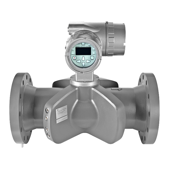
GE Measurement Sentinel LCT4 User Manual (172 pages)
Ultrasonic Flow Meter
Brand:
GE Measurement
| Category:
Measuring Instruments
| Size: 15 MB
Table of Contents
Table of Contents
7
Chapter 1. Features and Capabilities
13
Overview
13
Applications
13
Advantages
13
Meter Components
14
Marking and Labeling
16
Theory of Operation
19
Transit-Time Method
19
Transducers
19
Multipath Design
20
Flow Profile
20
Maximum and Minimum Flow
21
Specifications
22
Operation and Performance
22
Meter Body
23
Electronics
27
Custody Transfer Approvals
28
Standards
29
Maximum Allowable Operating Data
29
Operating and Storage Temperatures
29
Operating Pressures
29
Weight
30
Flowrates
31
Allowable Fluids
31
Loads and Forces
32
Description of Different Operating Conditions
32
Certification
33
Pressure Equipment Directive (PED)
33
Canadian Registration Number (CRN)
33
Custody Transfer Performance Approvals
33
List of Reference Drawings and Documentation
34
Wiring Diagrams
34
Outline and Installation Diagrams
34
Manuals
34
Disclaimer
35
Warnings and Cautions
35
Chapter 2. Installation
37
Installation Guidelines
37
Bill of Materials
37
Unpacking
38
Inspection
38
Mechanical Installation
39
Location
39
Installation Precautions
41
Lifting Instructions
42
Installing the System
43
General Piping Rules
43
Guidelines for Installing Pipe Insulation
45
Making Electrical Connections
46
Removing the Covers
47
Cable Tie-Down Posts
48
Wiring the Line Power
49
Wiring the Serial Port
51
Wiring the Modbus Communications Line (Optional)
51
Wiring the Alarm Relay
52
Wiring the 4-20Ma Analog Input (Optional)
53
Wiring the Frequency/Totalizer Output
57
Wiring the 4-20 Ma Analog Output
58
Chapter 3. General Programming
69
Introduction
69
Keypad Features
69
Indicator Lights
70
The Magnetic Stylus
70
Program Menu Options
71
Channel Program
71
Composite Program
71
Advanced Program
71
Unlocking and Locking
71
Unlocking the Sentinel LCT4
71
Locking the Sentinel LCT4
72
Setting Security
74
Edit Passcodes
74
Security Timeout
74
Set Security
74
Channel Programming
74
Activating a Channel/Path/Chx (Status)
74
Entering Fluid Data (Not Supported at this Time)
75
Entering Signal Parameters
77
Entering Error Limits
77
Composite Programming
79
Entering Fluid Type
79
Entering Signal Parameters
80
Setting up Input Data Feeds
81
Setting up API (Additional Option)
81
Configuration
83
Inputs/Outputs
84
Analog Output
85
Frequency/Totalizers
85
Alarms
87
Analog Inputs (Additional Option)
88
RTD (Additional Option)
89
Display
90
Calibration of Analog Output
90
User Security
91
Edit Passcodes
91
Security Timeout
91
Set Security
91
Factory Status
92
Chapter 4. MODBUS Communications
93
Introduction
93
Setting up MODBUS Communications
93
Chapter 5. HART Communications
99
Introduction
99
Wiring the HART Interface
99
Flowmeter Software Setup
100
Product Interfaces
100
Process Interface
100
Host Interface
101
Device Variables
101
Dynamic Variables
105
Status Information
105
Device Status
105
Extended Device Status
105
Additional Device Status
106
Universal Commands
107
Common-Practice Commands
107
Supported Common Practice Commands
107
Burst Mode Commands
108
Catch Device Variable Command
108
Device-Specific Commands
109
Command 181 (0Xb5): Clear Totals
109
Tables
110
HART Engineering Units
110
Performance
113
Sampling Rate
113
Power-Up
113
Device Reset
113
Self-Test
113
Command Response Delay
114
Busy and Delayed Response
114
Long Messages
114
Non-Volatile Memory
114
Operating Modes
114
Write Protection
114
Write Protect Switch
114
Totals Protect Switch
114
Capability Checklist
115
Default Configuration
116
Manufacturer and Device ID
116
Chapter 6. Maintenance
117
Calibration
117
Updating Sentinel LCT4 Instrument Software
117
Checking the Meter Software
121
Trimming 4-20 Ma Loop Using the Keypad
122
Hardware Maintenance and Inspection
123
Servicing the Pipe Flange Interface
124
Servicing the Sensor Ports or Transmitter Interface
124
Spare Parts
126
Installing Replacement Parts
127
Chapter 7. Troubleshooting
129
Introduction
129
Error Codes
129
E0: no Error
130
E1: Low Signal
130
E2: Soundspeed Error
130
E3: Velocity Range Error
130
E4: Signal Quality Error
131
E5: Amplitude Error
131
E6: Cycle Skip, Acceleration Error
131
E7: Analog Output Error
131
E13: Settle Tracking AGC
131
E14: Tracking Seek Mode
132
E15: Active Tw Error
132
E16: Totalizer Overflow Error
132
E17: Temperature Input Error
132
E18: Pressure Input Error
132
E19: Density Input Error
133
E20: Special Input Error
133
E21: API Error
133
E22: Degraded Performance Error
133
E23: Reduced Accuracy Error
133
E24: Low SNR Error
134
E29: Stale Data Error
134
E30: Channel Disabled
134
Displaying Diagnostic Parameters
135
Fluid and Pipe Problems
138
Fluid Problems
138
Pipe Problems
139
Transducer Problems
139
Audit Trail
139
Audit Log
139
Audit Log (Cont.)
140
Reading Audit Log Records
142
Formatting and Viewing Log Records
143
Uncertainty in Flow Rate for a Non-Insulated Meter
144
Appendix A. Menu Maps
145
List of Menu Maps
145
Appendix B. CE Mark Compliance and High Noise Areas
155
Introduction
155
EMC Compliance
155
Appendix C. Service Record
157
Introduction
157
Data Entry
157
Advertisement
Advertisement
Related Products
GE Measurement Categories
Measuring Instruments
More GE Measurement Manuals
Login
Sign In
OR
Sign in with Facebook
Sign in with Google
Upload manual
Upload from disk
Upload from URL