Advertisement
Advertisement
Table of Contents

Subscribe to Our Youtube Channel
Related Manuals for Sportop E770


Summary of Contents for Sportop E770
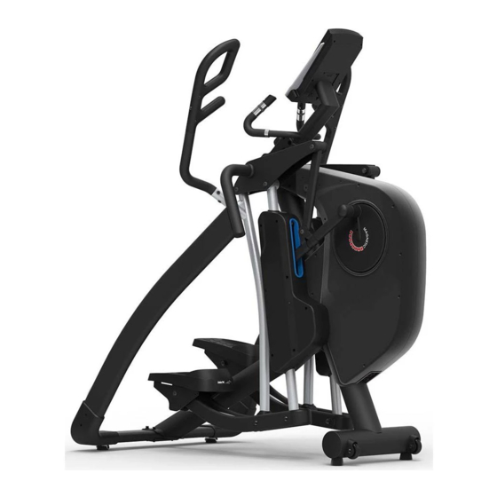
- Page 1 CHANGEABLE STRIDE ELLIPTICAL MODEL:E770 Owner’s Operating Manual ENGLISH...
- Page 2 Warning: Unpacking Caution: A. Lay the box down flat so that the lid is able to be lifted. Unpack the handle bars, side supporting tubes, pedal supporting tube and owners manual. Remove the top polyfoam pieces #1 & #2 and finish up packing the console, console supporting tube, central supporting tube, pedal supporting tube, and hardware bag, leaving the main frame(A) and bottom polyfoam pieces #3 &...
- Page 3 2#465 .+56 Console supporting Main frame tube E2 Handle bar (R) E1 Handle bar (L) C1 Side connecting tube (L) B1 Pedal supporting C2 Side connecting tube (R) tube (L) Side tube cover set B2 Pedal supporting tube (R) Side tube cover set Console F1 Central supporting tube...
- Page 4 2#465 .+56 (J2) Screw M4X16 (J3) Screw M4X6 (J4) Screw M8X55 (J5) Washer M8 (J6) Screw M8X20 (J8) Washer M12 (J9) Nut M12 (J10) Screw M12X109 (J7) Screw M12X73 (J13) Screw M8X16 (J14) Screw M5 5m/m 4m/m 6m/m*2 - 2 -...
- Page 5 CENTRAL SUPPORTING TUBE (F1) ASSEMBLY Step 1. Remove the two preassembled screws (J1) from the main frame (A) and two screws (J1) from the central supporting tube (F1). Step 2. Assemble the central supporting tube (F1) onto the main frame (A) use the previously removed screws (J1) to join them.
- Page 6 RIGHT SIDE CONNECTING TUBE ASSEMBLY Step 1. As shown in Views (A & B) Assemble the right side connecting tube (C2) assembly to the machine. Step 2. As shown in View (A) Assemble the tube (C2) assembly onto the upper main frame.
-
Page 7: Handle Bar Assembly
PEDAL SUPPORTING TUBE ASSEMBLY Step 1. As shown in View (C) Connect the right pedal supporting tube (B2) to main frame (A). Use the tools provided to tighten screw (J7), washer (J8) and nut (J9). VIEW C Step 2. As shown in View (D) Connect and align the right lower pedal supporting tube (B5) to the front pedal supporting tube on the main frame (A). -
Page 8: Console Assembly
CONSOLE SUPPORTING TUBE AND BOTTLE HOLDER ASSEMBLY Step 1. Connect wires (D1 & D2) from the console supporting tube (D) to wires (A1 & A2) from the main frame (A). VIEW G Step 2. Slide the console supporting tube (D) onto the main frame (A). -
Page 9: Power Cord Assembly
POWER CORD ASSEMBLY Attach the power cord jacket into the power socket on the main frame before plugging the power cord plug into the wall outlet. Turn the AC power switch on. Flip the ON/OFF switch to the ON position. "0"... -
Page 10: How To Transport The Machine
HOW TO TRANSPORT THE MACHINE If the machine needs to be transported to a different location, make sure that the pedal lock knob is at “LOCK” position. Lift up both sides of the rear supporting tubes until the front transportation wheels are touching the ground. You may now move the machine to the desired location. - Page 11 HOW TO ADJUST STRIDE BY INCLINE MOTORIZED Depending on the personal demand to change the stride in different distance 18”, 20”, 22”, 24”, and 26” as the LED sensor displayed. There are 5 stride control quick keys, press one of the 18”...
-
Page 12: Button Functions
BUTTON FUNCTIONS To make upward adjustment to each function data or increase training resistance. DOWN To make downward adjustment to each function data or decrease training resistance. ENTER To confirm all settings. To start or stop workout. START Turn the START/ STOP joggle wheel under standby mode, / STOP it can be a quick start key to the Manual Program. -
Page 13: Programming Mode
CALORIES Accumulates calories consumption during training from 0 to maximum 990 calories. Each unit for increase or decrease is 10 KCL. (This data is a rough guide for comparison of different exercise sessions which can not be used in medical treatment.) PULSE User may set up target pulse from 0 - 30 to 230 WATTS... - Page 14 2. Use UP/DOWN joggle wheel to select the program you want and press ENTER to confirm. Or press START/STOP button to start MANUAL mode immediately. FIGURE 8 FIGURE 9 FIGURE 10 FIGURE 11 FIGURE 12 QUICK START IN MANUAL 1. Press ENTER to enter MANUAL program, and the screen is blinking (FIGURE 13). 2.
-
Page 15: Manual Mode
MANUAL MODE 1. After selecting MANUAL mode (FIGURE 13), user can use UP/DOWN joggle wheel to increase or decrease level (from 1 to 16) and press ENTER to confirm. 2. User may preset exercise data (TIME, DISTANCE, CALORIES, PULSE), and press START/STOP to start exercise. -
Page 16: Program Mode
PROGRAM MODE 1. After enter PROGRAM mode, user and turn the UP/DOWN joggle wheel to select program profile from P1 to P12, then press ENTER to confirm. 2. User can preset the TIME data then press START/STOP to start exercise. 3. -
Page 17: User Program
USER PROGRAM 1. After enter USER PROGRAM mode, the first column of the profile is blinking (FIGURE 25). User may turn the joggle wheel to adjust the resistance level (FIGURE 26) to create his / her own profile. 2. After setting (from column 1 to column 20), user may hold on pressing MODE button for 2 seconds to quit profile setting and enter TIME setting. -
Page 18: Heart Rate Control
HEART RATE CONTROL 1. After enter HEART RATE CONTROL mode, the screen will show heart rate percentage 55%, 75%, 90% and TARGET. User may select heart rate percentage by turning UP/ DOWN joggle wheel for training. 2. User can preset the TIME data then press START/ STOP to start exercise. 3. -
Page 19: Watt Constant
WATT CONSTANT 1. In standby mode, select WATT and press ENTER to enter. 2. The preset watt value 120 is flashing on screen, use UP/ DOWN joggle wheel to set target value from 10 to 350. Pressing START button to start training. 3. - Page 20 FIGURE 39 FIGURE 40 NOTE: 1. When user stop pedaling for 4 minutes, computer will enter into power save mode, all setting and exercise data will stored until user start exercise again. 2. This computer requires 9V, 1A adaptor. 3. When computer act abnormal, please plug out the adaptor and plug in again.
Need help?
Do you have a question about the E770 and is the answer not in the manual?
Questions and answers
The CT is making som high noises when in use - how to get rid of this? Oil?