
Subscribe to Our Youtube Channel
Related Manuals for Sportop E 8000P


Summary of Contents for Sportop E 8000P
-
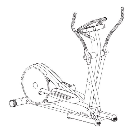
Page 1: Elliptical Trainer
ELLIPTICAL TRAINER E 8000P MODEL: Owner's Operating Manual ENGLISH... - Page 2 F1-L F2-R J1-L J1-R - 1 -...
- Page 3 - 2 -...
- Page 4 ASSEMBLY FOR REAR STABILIZER Attach the Rear Stabilizer (C)(the Rear Stabilizer will have wheels) to the bracket at the back of the Main Frame (A) Use two bolts (L1), two Arc Washers (L2) and two Nuts (L3.) ASSEMBLY FOR FRONT STABILIER Before you attach the Front Stabilizer(D) to the brackets on the Main Frame (A) you will need to put two bolts (L6)
- Page 5 ASSEMBLY FOR CENTRAL SUPPORT TUBE Connect the Cable (A7) from the Main Frame(A) to the Cable (B11) coming out of the Central Support Tube(B.) Once they are connected firmly, insert the Central Support Tube (B) into the Main Frame (A.) Please make sure when attaching the two ends of the tube together that cables are not pinched.
- Page 6 ASSEMBLY FOR PEDAL SUPORT Start with the right side and take the Pedal Support Tube (J1-R) and pull up the connected tube (J11) into the straight position. Once in the upright position attach to the Connected Tube (K) making sure firmly clicking in place. Repeat steps above for the left side.
- Page 7 ASSEMBLY FOR PEDAL SUPORT TUBE Slide the left side of the pedal support tube (J1-L) into the rear hole on the main frame (A.) Attach using the nut (L11.) Repeat the process on the right side. KEEP THE MACHINE STABLE You can also use the adjustable end cap (D3-2) to adjust for uneven or unlevel floors.
- Page 8 ASSEMBLY FOR SIDE PEDAL JOINT COVERS Attach the right and left side of the Pedal Joint Cover (H2-R & H2-L) onto the Pedal Support Tube (J1-R), secure using four bolts (L12) H2-L H2-R J1-R ASSEMBLY FOR PEDALS There are three positions to place the pedals. Starting with the right pedal (H3-R) on the Pedal Support Tube (J1-R) and using washers (L8) and two Star Knobs (L13) attach firmly to one of the positions on the Pedal Support Tube (J1-R.) Repeat the process above for the left side.
- Page 9 ASSEMBLY FOR FRONT HANDLEBAR Step1. Connect sensor wires(F7) and sensor wires(B12) Step2. Insert the front handlebar(F1-L & F2-R) into the central support tube. F2-R F1-L Step 3.Twist and connect the front handlebar (F1-L & F2-R) as shown on (Figure 8-2). F2-R F1-L F2-R...
- Page 10 G1-R G1-L H5-L H5-R ASSEMBLY FOR SIDE HANDLEBAR Slide side handlebar(G1-L & G1-R) into connect tube and secure it by bolts(L15). ASSEMBLY FOR WATTER BOTTLE HOUSING Step 1. Assembly the bottle housing(H4) with the central support tube and secure it by screw(L17). Step 2.
- Page 11 H1-FRONT H1-BACK ASSEMBLY FOR SIDE HANDLEBAR JOINT COVER Starting on the right side connect the front of the Handlebar Joint Covers (H1-Front) to the back of the Handlebar Joint Covers (H1-Back) using two screws (L16). Repeat the steps above for the left hand side of the Handlebar Joint Covers (H1-Front &...
-
Page 12: How To Move The Machine
HOW TO MOVE THE MACHINE Stand at the front of the machine and lift it up until the weight of the machine is transferred to the transport wheel (located on the Rear Stabilizer (C.) Now the machine can be rolled to a new location if necessary. - Page 13 - 12 -...
-
Page 14: Parts List
PARTS LIST DESCRIPTION Q'TY P/N DESCRIPTION Q'TY P/N DESCRIPTION Q'TY MAIN FRAME BUSHING H3-R PEDAL (R) A2-1 PULLEY AXLE BEARING WATER BOTTLE HOUSING A2-2 NUT BEARING HOUSING H5(L) BACK COVER(L) A2-3 BELT PULLEY BEARING HOUSING H5(R) BACK COVER(R) A2-4 HEXAGON WASER FLAT WASHER WATER BOTTLE A2-5 BEARING... -
Page 15: Exercise Computer
EXERCISE COMPUTER Monitor instruction manual 1. Plug the power supply (AC adaptor). 2. The monitor displays all segments for 2 seconds. [If you press RESET button for over 2 seconds, the monitor will display all segments for 2 seconds for a new start.] 3. - Page 16 droped to level 1 at the moment] as a proection implement. If you see the symbol --- and on the monitor, it means your current speed is too fast and the resistance has been droped to the minium level. At the moment, the monitor alarms "bi-b-bi" per second to remind you decreasing training speed.
- Page 17 heart rate figures for training. 3-1 The training resistance level is not available to be adjusted by buttons operation if you are training in TARGET H.R. mode. 3-2 The resistance level will be auto adjusted by the monitor according to your actual heart rate figure. If your current heart rate figures is under preset, the resistance level will be increased 1 level per 30 seconds till level 16 or the target heart rate figures is achieved.
- Page 18 PULSE The monitor can detect both chest pulse and hand pulse, the chest pulse is priority. It means if you hold both hands on handlebar grip sensors and wear on the chest blet together, the monitor will display chest pulse only. If you would like to have hand pulse readout, please do not wear on the chest belt when you hold on handgrip sensors.
Need help?
Do you have a question about the E 8000P and is the answer not in the manual?
Questions and answers
Need a replacement belt
The parts list in the manual includes a "BELT PULLEY" (A2-3), but it does not specify a separate replacement belt. To find a replacement belt for the Sportop E 8000P, you may need to check with the manufacturer or an authorized parts supplier.
This answer is automatically generated