Table of Contents
Advertisement
Service Literature
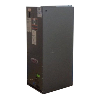
ELITE 10 CB29M and ELITE 12 CB30M SERIES UNITS
The Elite 10 CB29M and Elite 12 CB30M are high efficiency
blower coils. Several models are available in sizes ranging
from 1-1/2 through 5 tons (5.3 through 17.6 kW). Both the
CB29M and CB30M are multi-position (upflow, downflow
or horizontal) units. The units come with a factory
installed check and expansion valve for cooling or heat
pump applications.
CB29M series units are designed to be matched with the
10 SEER air conditioner and heat pump line, and the
CB30M series units are designed to be matched with the
12 and 13 SEER air conditioner and heat pump lines.
Corp. 9711–L7
INCLUDING ECB29 ELECTRIC HEAT
CB29M
Page 1
While these blower coil units are designed to be primarily
matched with these outdoor units, they may be matched
with other air conditioners or heat pumps as noted in the
rating information.
ECB29 electric heat, in several voltages and kW sizes, can
be field installed in the CB29M and CB30M cabinets.
Information contained in this manual is intended for use
by experienced HVAC service technicians only. All specifi-
cations are subject to change. Procedures outlined in this
manual are presented as a recommendation only and do
not supersede or replace local or state codes.
CB29M
CB30M
CB30M
Advertisement
Table of Contents


Need help?
Do you have a question about the ELITE 10 CB29M Series and is the answer not in the manual?
Questions and answers