Lennox CBX25UH018 Installation And Service Procedure
Hide thumbs
Also See for CBX25UH018:
- Installation and service procedure (23 pages) ,
- Installation instructions manual (16 pages)
Advertisement
Table of Contents
- 1 Table of Contents
- 2 Unit Dimensions
- 3 Specifications / Electrical Data
- 4 Model Number Information
- 5 Blower Data
- 6 All Air Data Measured External to Unit with 1 Inch
- 7 Application
- 8 Unit Components
- 9 Optional ECB25 Electric Heat
- 10 Configuration Modification
- 11 Condensate Drain
- 12 Electrical Connections
- 13 Wiring Diagrams
- 14 Start-Up Operations
- 15 Sequence of Operations
- 16 Performance Checklists
- Download this manual
Service Literature
WARNING
Improper installation, adjustment, alteration, service or
maintenance can cause personal injury, loss of life, or
damage to property.
Installation and service must be performed by a licensed
professional installer (or equivalent) or a service agency.
CAUTION
Physical contact with metal edges and corners while
applying excessive force or rapid motion can result in
personal injury. Be aware of, and use caution when
working near these areas during installation or while
servicing this equipment.
IMPORTANT
The Clean Air Act of 1990 bans the intentional venting of
refrigerant (CFCs, HCFCs and HFCs) as of July 1, 1992.
Approved methods of recovery, recycling or reclaiming
must be followed. Fines and/or incarceration may be
levied for noncompliance.
INSTALLATION AND SERVICE PROCEDURE
Corp. 1241-L9
December 2012
Revised August, 2018
CBX25UH Series
Page 1
Table of Contents
. . . . . . . . . . . . . . . . . . . . . . . . . . . .
. . . . . . . . . . . . . . . . . . . . . . . . . . . . . . . .
. . . . . . . . . . . . . . . . . . . . . . . . . . . . . . . . .
. . . . . . . . . . . . . . . . . . . . . . . . . . . .
. . . . . . . . . . . . . . . . . . . . . .
. . . . . . . . . . . . . . . . . . . . . . . . . . .
. . . . . . . . . . . . . . . . . . . . . . . .
. . . . . . . . . . . . . . . . . . . . .
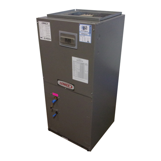
The CBX25UH are high-efficiency air handler. Several models
are available in sizes ranging from 1-1/2 through 5-tons. The
CBX25UH is designed for HFC-410A refrigerant.
CBX25UH series units are designed to be matched with either
a13 SEER air conditioner or heat pump, but can be matched
with other air conditioners or heat pumps as noted in the rating
information. See Product Specification bulletin.
This air handler is designed for indoor installation only. As
shipped, the unit is ready for installation in either upflow or
horizontal left-hand. Field modifications are required for
right-hand air discharge applications. Electric heat, down
flow air discharge application kits, air filters and other
various accessories are available and listed in the
CBX25UH Product Specification bulletin for ordering.
All units come with a factory installed check/expansion
valve.
Information contained in this manual is intended for use by
experienced licensed HVAC service technicians only. All
specifications are subject to change. Procedures outlined in
this manual are presented as a recommendation only and do
not supersede or replace local or state codes.
CBX25UH
2
. . . . . . . . . . . . . . . .
3
. . . . . . . . . . . . . . . . . . .
4
4
6
6
. . . . . . . . . . . . . . . . .
7
. . . . . . . . . . . . . . . . . . .
10
16
17
19
. . . . . . . . . . . . . . . . . . . .
20
21
Advertisement
Table of Contents

Related Manuals for Lennox CBX25UH018


Summary of Contents for Lennox CBX25UH018
-
Page 1: Table Of Contents
INSTALLATION AND SERVICE PROCEDURE Corp. 1241-L9 CBX25UH December 2012 Service Literature Revised August, 2018 CBX25UH Series Table of Contents Unit Dimensions ......Specifications / Electrical Data . -
Page 2: Unit Dimensions
Specification and Electrical Data Unit Dimensions - inches (mm) 3/4 (19) LINE VOLTAGE Right, Left and Top LOW VOLTAGE Right Side Only AIR FLOW CONDENSATE DRAIN PIPING PLATE (4) (2−1/4 x 3−3/4) FILTER ACCESS SUCTION LINE LIQUID LINE (19) (Opening) (Opening) 1−3/4 2−1/2... -
Page 3: Specifications / Electrical Data
Specification and Electrical Data SPECIFICATION General Model Number CBX25UH018 CBX25UH024 CBX25UH030 CBX25UH036 Data Nominal tonnage Connections Suction/Vapor line (o.d.) in. sweat Liquid line (o.d.) in. sweat Condensate in. fpt (2) 3/4 (2) 3/4 (2) 3/4 (2) 3/4 Indoor 3.11 3.56... -
Page 4: Model Number Information
Model Number Identification CB X 25 UH − 030 − 230 − 1 Unit Type Minor Revision Number CB - Air Handler Voltage Refrigerant Type 230 = 208/230V-1 phase-60hz X = HFC-410A Nominal Cooling Capacity Series 018 = 1.5 tons 024 = 2 tons Configuration 030 = 2.5 tons... -
Page 5: All Air Data Measured External To Unit With 1 Inch
Table 1. Specification and Electrical Data Blower Performance (3-Speed PSC) - 240V (CFM @ ESP. - in. W. C.) Air Handler Blower Speed .10” WC .20” WC .30” WC .40” WC .50” WC Model Low (Red) Med (Blue) High (Black) Low (Red) Med (Blue) High (Black) -
Page 6: Application
All major blower coil components must be matched 3. Once demand is met, motor runs at 100% for 45 according to Lennox recommendations for the unit to be seconds. covered under warranty. Refer to the Product Specification Motor ramps down to stop. -
Page 7: Optional Ecb25 Electric Heat
4. Remove the no-heat seal plate in the air handler frame. Optional ECB25 Electric Heat See figure 6. The electric heat sections provide field installed electric heat for air handler units. OFFSET Table 2 shows the available heat sections. Refer to the Product Specifications for heat section applications. - Page 8 IMPORTANT - To remove knockouts, knock them out in the 2. Locate the one clip which is located on the right side (see arrow) of each breaker (see figure 8). The clip same direction the punch did. Always start with the smallest secures the circuit breaker to the mounting bracket.
- Page 9 3. Flip the breaker so that the wires attached to the circuit Refer to figure 31 for typical low voltage field wiring for air breakers terminals are on the left side (see figure 9). handler/condensing unit and heat pump applications. Figure 32 is a diagram of the air handler connections and 4.
-
Page 10: Configuration Modification
Configuration Modification CIRCUIT BREAKER COVER (BACKSIDE) UPFLOW APPLICATION 1. The air handler must be supported on the bottom only and set on solid floor or field‐supplied support frame. Securely attach the air handler to the floor or support frame. 2. If installing a unit in an upflow application, remove the horizontal drain pan. - Page 11 NOTE — When the unit is installed in horizontal 1. Remove and set aside blower and coil access covers. applications, a secondary drain pan is recommended. 2. Remove bracket(s) securing pan(s) to unit as Refer to local codes. illustrated in figures 18 and 19. NOTE —...
- Page 12 IMPORTANT On units of this type, where the blower “draws” rather than “blows” air through the coil, traps must be installed in the con densate drain lines (primary and auxiliary, if used). Traps prevent the blower from drawing air through the drain lines into the air supply.
-
Page 13: Condensate Drain
TRAPS MUST BE DEEP ENOUGH TO OFFSET MAXIMUM STATIC DIFFERENCES — GENERALLY, TWO INCHES (51MM). TRAP DEPTH TO APPROVED LENNOX P-TRAP 49P66 REQUIRES A LARGER INSTALLATION SPACE THAN THE J-TRAP 91P90. DRAIN FOR NEGATIVE PRESSURE COILS (BLOWER DRAIN LINE SHOULD PIPE NIPPLE PROVIDED IN BAG ASSEMBLY - SCH 80, 3/4”... - Page 14 INSTALL CONDENSATE DRAIN DUCT SYSTEM The air handler is provided with flanges for the connection 1. Remove the appropriate drain knockouts. If necessary, of the plenum and ducts. The air handler is equipped with remove the indoor coil assembly from the cabinet. flanges that can form a filter rack for the installation of the air 2.
- Page 15 7. Make sure outdoor unit has been put in place according 5. Apply insulation over the suction line and TXV bulb and to the Installation Instructions and is connected to the secure with tape or cable ties.. refrigerant lines. RELOCATING TXV BULB Relocation of the TXV bulb to the exterior of the unit cabinet is highly recommended.
-
Page 16: Electrical Connections
1. Disconnect all power supplies. Electrical Connections 2. Remove the air handler access panel. 3. Route the field supply wires to the air handler electrical WARNING connection box. 4. Use UL-listed wire nuts to connect the field supply Electric shock hazard! - Disconnect all conductors to the unit black and yellow leads, and the power supplies before servicing. -
Page 17: Wiring Diagrams
Wiring Diagrams THERMOSTAT AIR HANDLER THERMOSTAT AIR HANDLER NOTE NOTE HEAT‐ONLY APPLICATION CONDITIONER THERMOSTAT HEAT PUMP UNIT UNIT AIR HANDLER COOLING‐ONLY APPLICATION THERMOSTAT AIR HANDLER CONNECT COMMON WIRE ONLY IF REQUIRED (REFER TO THE APPROPRIATE THERMOSTAT INSTALLATION INSTRUCTIONS) NOTE HEAT PUMP APPLICATION WITH AIR CONDITIONER ELECTRIC HEAT UNIT... - Page 18 THERMOSTAT AIR HANDLER CONDENSING UNIT Air Handler THERMOSTAT HEAT PUMP UNIT AIR HANDLER CONNECT COMMON WIRE ONLY IF REQUIRED (REFER TO THE APPROPRIATE S23 OUTDOOR THERMOSTAT THERMOSTAT INSTALLATION (IF USED) INSTRUCTIONS) K22 EM HEAT RELAY Heat Pump Application With Electric Heat Figure 31.
-
Page 19: Start-Up Operations
Figure 32. Unit Wiring Diagram - Electric Heat and Air Handler Has the condensate line been properly sized, run, Start-Up Operation trapped, pitched, and tested? Is the duct system correctly sized, run, sealed, and NOTE - Refer to outdoor unit installation instructions for insulated? system start-up instructions and refrigerant charging Have all cabinet openings and wiring been sealed? -
Page 20: Sequence Of Operations
At the completion of the cooling demand the indoor blower Are all access panels in place and secure? and outdoor unit should cycle off. Air handler should cycle CHECK BLOWER OPERATION off 45 seconds after the outdoor unit shuts off. Set thermostat to FAN ON. -
Page 21: Performance Checklists
Performance Checklists Installing Contractor’s Name_______________________ Installing Date_______________________________ Installing Contractor’s Phone_______________________ Air Handler Model #___________________________ Job Address____________________________________ Thermostat Line Voltage SUPPLY Disconnect Switch Integrated Control Temperature Duct Blower Motor Amps System Electric Heat Amps Duct Static RETURN Filter Drain Line DUCT SYSTEM TOTAL EXTERNAL STATIC (dry coil) dry coil wet coil... - Page 22 Installing Contractor’s Name_______________________ Installing Date_______________________________ Installing Contractor’s Phone_______________________ Air Handler Model #___________________________ Job Address____________________________________ Line Voltage Disconnect Switch Thermostat Integrated Control Duct System Duct System Filter RETURN SUPPLY Electric Heat Amps Blower motor Amps Drain Line Duct Static Temperature DUCT SYSTEM TOTAL EXTERNAL STATIC (dry coil) dry coil wet coil...
Need help?
Do you have a question about the CBX25UH018 and is the answer not in the manual?
Questions and answers