Sign In
Upload
Manuals
Brands
TECO Manuals
Controller
TP03 PLC
TECO TP03 PLC Manuals
Manuals and User Guides for TECO TP03 PLC. We have
1
TECO TP03 PLC manual available for free PDF download: User Manual
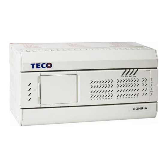
TECO TP03 PLC User Manual (152 pages)
Programmable Logic Controller
Brand:
TECO
| Category:
Controller
| Size: 2 MB
Table of Contents
Tp03 Programmable Logic Controller Teco Electric & Machinery Co., Ltd.
2
Table of Contents
2
Chapter 1 Tp03 Introduction
6
Model Type Description
8
Product Type
9
Expansion Module List
12
Programming Tool
14
Accessory List
15
System Configuration
16
OP07/08-TP03 Cable (TP03-302MC) Specification
17
TP03-302PC Cable Specification
18
TP03 PC/PDA Port Connect with HMI by RS-422
19
Chapter 2 Basic Unit Specification
23
AC Type Power Supply Specification
25
General Features for Basic Unit
26
Environment Specification
27
Digital Input/Output
28
Communication Ports
30
Function Description for 3 Communication Port
31
Three Communication Ports Description
33
Data Link
43
RS/MBUS Instruction
44
High Speed Counter
46
Function
48
Application Example for 1 Phase High Speed Counter
49
Phase 2 Input
50
Action of 2 Phase Input Signal
51
Common Consideration:
52
Interruption Input
53
Pulse Output
54
Built-In Memory and Memory Card (TP03-1ME)
55
Password
56
Potentiometer
58
Battery
59
Chapter 3 Expansion Unit Specification
61
Outline Dimension
62
Electric Specification
63
TP02-16EYR Specification
64
TP02-16EYT Specification
65
TP02-16EMR Specification
66
TP02-32EMR Specification
67
TP03-16EMR Specification
68
TP03-16EMT Specification
69
TP03-16EYR Specification
70
TP03-16EYT Specification
71
TP03-16EXD Specification
72
Analogue Expansion Unit
73
Data Register and Channel of Analog Expansion Module
74
Setting the System Memory
75
General Specification for Analog Expansion Unit
77
Wiring for Analog Expansion Module
78
Electric Specification
80
TP03-8AD Specification
81
TP03-4RD Specification
82
TP03-4TM Specification
83
TP02-2DA+ Specification
84
TP03-2DA Specification
85
TP03-3MA Specification
86
How Many Expansion Unit Can be Connected to Base Unit
88
For Example
89
Chapter4 Dimension And Installation
90
Outline Dimension
91
Basic Unit
91
TP02 Expansion Unit
92
TP03 Expansion Unit and Power Unit
93
TP03 Communication Unit
93
Installation
94
Ambient Environment
94
Installation of Basic Unit and Expansion Unit
94
Directly Installation
95
DIN Rail Installation
97
Installation for Expansion Cable and Termination Connector
97
Chapter 5 Wiring
99
Wiring
100
Basic Unit Wiring
101
Wiring Power Supply and Specification
101
Input Wiring at Power Supply Terminal
101
Protection Circuit
102
Input Wiring
103
Output Wiring
104
Expansion Unit Wiring
106
Input Wiring for Expansion Unit
106
Output Wiring for Expansion Unit
107
Wiring Consideration
108
Wiring Consideration for Input Power Terminal
108
When Built in DC24V Power Supply Share Common Terminal with External Power
108
Wiring Consideration for Input Terminal
108
Wiring Consideration for Different Input Devices (Sensor/ Switch
109
Leakage Current of Input Component
110
Output Terminal Wiring Consideration
111
Surge Current from Indicator Load
111
Surge Voltage of Inductive Load
111
Driving a Light Load
112
Lifespan of Relay
112
Wiring Consideration for TP03 HT Type PLC
112
Solving Noise Problem
113
Power Source Noise
113
Solving Thunder Stroke Problem
114
Anti-Noise for Expansion Cable
115
Anti-Noise for I/O Wiring
115
Trial Run
116
Chapter 6 Trial Run
117
Trial Run
117
Before Trial Run
117
Trial Run Step
118
Maintenance and Inspection
119
Basic Unit
119
Expansion Units
119
General Items
119
Periodical Inspection
119
Troubleshooting
120
LED Indicator Status
120
Preparation for Troubleshooting
120
Presumption of Troubleshooting Procedure
120
Check the Following Again
121
Troubleshooting Procedure
122
Troubleshooting Procedure - 1
122
Troubleshooting Procedure - 2
122
Troubleshooting Procedure - 3
122
Troubleshooting Procedure - 4
122
Troubleshooting Procedure - 5
122
Troubleshooting Procedure - 2
123
Troubleshooting Procedure - 3
124
Troubleshooting Procedure - 5
125
Chapter 5 Wiring
126
Chapter 7 Instruction List
126
Step Instruction :STL, RET
128
Application Instruction List
129
Table of Contents
133
Chapter 8 Special Relay
134
Clock Device(M
134
Operation Flags(M
134
PC Status (M)
134
PC Status(D
135
Rtc(D
135
PC Mode(D
136
PC Operation Mode(M
136
Step Ladder Flags (M)
136
Interruption Disable(M
137
Step Ladder Flags (D)
137
UP/DOWN Counting Set Device(M
137
Communication and Link (M) I
139
Devices(M
139
Error Detection(D
139
Communication and Link (D) I
141
Communication and Link (D) II
141
Communication and Link (M) II
143
Communication and Link (D) II
144
Communication and Link (M) II
141
Expansion (M
145
High Speed and Position (M)
145
PWM Output(D
145
High Speed and Position(D
146
Op07/08(M
147
Op07/08(D
148
Ad/Da (D)
149
Ad/Da (M)
149
Advertisement
Advertisement
Related Products
TECO TSTA Series
TECO TSTA 15
TECO TSTA 20
TECO TSTA 30
TECO TSTA 50
TECO TSTA 75
TECO TPO40CFWBG
TECO TPO40HFWBG
TECO TPO35CFALHBE
TECO TPO35CFWCT
TECO Categories
Inverter
Air Conditioner
Refrigerator
Chiller
Controller
More TECO Manuals
Login
Sign In
OR
Sign in with Facebook
Sign in with Google
Upload manual
Upload from disk
Upload from URL