
Related Manuals for Jasic TIG200PACDC PFC


Summary of Contents for Jasic TIG200PACDC PFC
- Page 1 TIG200PACDC PFC TIG200PACDC IGBT INVERTER WELDER Copyright©2022 Shenzhen JASIC Technology Co., Ltd.
- Page 2 JASIC website at www.jasictech.com. Disclaimer Shenzhen JASIC Technology Co., Ltd. solemnly promises that this product is manufactured according to relevant domestic and international standards, and that this product conforms to EN60974-1 International Safety Standard. Patents protect the relevant design scheme and manufacturing technology adopted in this product.
-
Page 3: Table Of Contents
Contents 1. Safety precautions ......................5 1.1. General safety ........................ 5 1.2. Other precautions ......................8 2. Description of symbols ....................... 9 3. Product overview ......................10 4. Technical parameters ....................... 11 5. Installation ........................13 5.1. External interface description ..................13 5.2. - Page 4 For your safety, please read this manual carefully before installing and operating this JASIC equipment. Pay extra attention to all content marked with " ". All operations must be carried out by professional, suitably qualified persons! Page 4...
-
Page 5: Safety Precautions
1. Safety precautions 1.1. General safety SAFETY INSTRUCTION These general safety norms cover both arc welding machines and plasma cutting machines unless otherwise noted. It is important that users of this equipment protect yourselves and others from harm or even death. - Page 6 Arc rays——May injure the eyes and burn the skin. Welding arc rays from all welding processes produce intense, visible and invisible (ultraviolet and infrared) rays that can burn eyes and skin. ·Wear an approved welding helmet fitted with an appropriate shade of filter lens to protect your face and eyes when welding or watching.
- Page 7 If you still do not fully understand or cannot solve the problem after reading the instructions in this manual, you should contact the supplier or JASIC's service center immediately for professional help.
-
Page 8: Other Precautions
1.2. Other precautions Warning! Location The machine should be located in a suitable position and environment. Care should be taken to avoid moisture, dust, steam, oil or corrosive gases. Place on a secure level surface and ensure that there is adequate clearance around the machine to ensure natural airflow. -
Page 9: Description Of Symbols
2. Description of symbols Warning! Read the Manual Current unit "A" WEEE tag Time unit "S" Overheat indicator Percentage Overcurrent indicator Frequency unit "Hz" VRD function indicator Lift TIG mode Warning tag Wireless remote control indicator Pairing of minimalist wireless MMA mode remote controller (optional) MMA current... -
Page 10: Product Overview
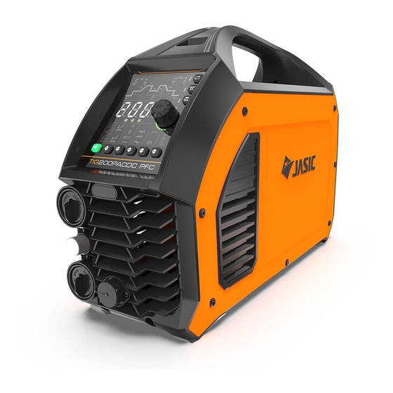
3. Product overview This is a digital inverter AC/DC welder featuring advanced technology which provides complete functions and excellent performance. It supports AC TIG (optional square wave, triangular wave and sine wave), AC pulse TIG, DC TIG, DC pulse TIG, SMAW (DC), and TIG spot welding (DC/AC), and can be widely used for precise welding of an extensive range of materials. -
Page 11: Technical Parameters
4. Technical parameters Item Unit Parameters Model TIG200PACDC PFC TIG200PACDC Input voltage AC115±15%~230V±15% AC230V±15% Input frequency 50/60 50/60 Rated input current 21.1@TIG 22.7@MMA 25@TIG 27@MMA (AC230V) Rated input current 32.2@TIG 34.1@MMA (AC115V) Rated input power 4.7@TIG 5.6@MMA 6.0@TIG 7.0@MMA (AC230V) Rated input power 3.5@TIG... - Page 12 Up-slope time 0~10 0~10 Down-slope time 0~10 0~10 Spot welding time 0.1-10 0.1-10 Arc start mode HF arc starting and lift arc starting HF arc starting and lift arc starting TIG: 25% TIG: 25% Duty cycle MMA: 30% MMA: 20% Efficiency Power factor 0.95...
-
Page 13: Installation
5. Installation Warning! All connections shall be made with the power supply is turned off. Warning! Electric shock may cause death; after power failure, there is still a high voltage on the equipment, do not touch the live parts on the equipment. Warning! Incorrect input voltage may damage the equipment. -
Page 14: Power Installation
5.2. Power installation Warning! The electrical connection of equipment shall be carried out by suitably qualified personnel. Warning! All connections shall be made after the power supply is off. Warning! Incorrect voltage may damage the equipment. Connect the welder with voltage grade corresponding to its input voltage. Do not connect it to the wrong grade. -
Page 15: Mma Electrode Holder And Earth Cable Connection
5.3. MMA electrode holder and earth cable connection (Wiring diagram) Pay attention to the polarity of wiring before performing MMA welding. Generally, there are two connection methods of DC welder: DCEN and DCEP. DCEN: The electrode holder is connected to the negative polarity, and the workpiece is connected to the positive polarity;... -
Page 16: Tig Welding Torch And Earth Cable Connection
5.4. TIG welding torch and earth cable connection 1) Ensure that the power switch is turned off. 2) Insert the cable plug with the earth clamp into the positive socket on the front panel of the welder and tighten it clockwise. 3) Insert the cable plug of the welding torch into the corresponding negative socket on the front panel of the welder and tighten it clockwise. - Page 17 ● If excessive cable must be wound up, refer to the following good practices Bad practice Good practice Do not wind up the excessive cable along the Wind up the same number of turns in the same direction. cable winding direction and the opposite direction, and stack them together.
-
Page 18: Wired Handheld Remote Controller Connection (Optional)
5.5. Wired handheld remote controller connection (optional) (Wiring diagram) Insert the aviation plug of the handheld remote controller directly into the corresponding aviation socket of the machine. NOTE: Please check that the machine supports wired handheld remote controller before installation. 5.6. -
Page 19: Control Panel
of the receiver module to the CN2 socket on the control panel PK-442. Note! Check with the seller whether the hardware and software versions of the machine support wireless remote controller before purchasing. 6. Control panel 6.1. HD digital panel 6.2. - Page 20 control function is disabled; and the welding current is controlled by the panel adjuster. If the overheat indicator is on, it indicates that the welder is in overheat protection and the has stopped output. Protection If the overcurrent indicator is on, it indicates that the indicators welder is in overcurrent protection and the has stopped output.
- Page 21 peak current. Peak current indicator. When the indicator is on, it indicates the welding current. Base current indicator. When the indicator is on, it indicates the pulse base current. Down-slope time indicator. When the indicator is on, it indicates the time until the peak current drops to the down finish current.
- Page 22 Press the welding mode button to switch the welding mode. 1. AC TIG indicator. When the indicator is on, it indicates that the machine is in AC TIG mode. AC output is suitable for welding aluminum and magnesium and their alloys. 2.
-
Page 23: Use Of Remote Controller
Stable arcs can increase the depth of the molten pool and improve the welding speed. Press the waveform selection key to switch the output waveform in AC mode. 1. Square wave indicator. When the indicator is on, it indicates that the machine is in square wave mode. Standard AC square waves quickly switch polarity, enjoying high arc stability, good dynamic characteristics, and strong ability to clean aluminum... - Page 24 paired, press and hold the pairing key of the wireless remote controller, or the remote control function key on the panel, and the wireless connection will be disconnected. After disconnecting, the display window of the welder will display "FAL", and the green indicator of the wireless receiver module will remain on.
-
Page 25: Other Functions
6.4. Other functions 6.4.1 Standby 1) Press and hold the "Current Setting Encoder" key for 2s to start the countdown. After the 3s countdown is over, the panel displays "F01"; press the key again to enter standby response time settings. 2) Rotate the "Current Setting Encoder"... - Page 26 Enter the Engineer mode 1) Press and hold the "Current Setting Encoder" key for 2s to start countdown. After the 3s countdown is over, the panel displays "F01". Rotate the "Current Setting Encoder" key clockwise to adjust the parameter to "F02", and press the key again to enter the input overvoltage and undervoltage protection settings.
- Page 27 100 —— —— —— —— —— —— —— —— —— —— pulse MMA —— —— —— —— —— —— —— —— —— —— —— 100 100 —— —— —— —— —— —— pulse Page 27...
- Page 28 Mixed —— —— —— 6.4.4 Barcode display View barcode Press and hold the Current Setting Encoder and Welding Mode keys simultaneously for 3s to view the machine barcode. Press any key or rotate the encoder to immediately exit the barcode display. If you do not perform any operation on the panel, the barcode automatically exits after 20s.
-
Page 29: Welding Function Operation
7. Welding function operation Warning! Before turning on the power supply make sure that the electrode holder or welding torch is connected to the output, do not touch the workpiece and earth clamp. Otherwise, an unexpected arc may be started when the power is turned on in the case of MMA by default. -
Page 30: Mma Operation
Spot ● ● ● ● ● ● × × × × × × × welding ● ● ● ● ● ● ● ● ● ● ● ● × ● ● ● ● ● ● ● ● ● ● ● ● pulse ×... -
Page 31: Tig Operation
start time is correlated with the arc starting current – the greater the current, the shorter the arc start time. 2. I (plus arc force current) = I (arc force current) + I (welding current). Use the electrode Δf diameter, set current and process requirements to determine the arc force current. High arc force settings lead to faster metal transfer and non-sticking electrode but with some spatter. - Page 32 lighting. ● Up-slope time (t2): Refers to the time as the current slowly rises from the initial current to the peak current, which can be determined according to the usage and process requirements. ● Peak current (I3): Set by the user according to the actual process requirements. ●...
- Page 33 tp-Pulse peak time T-Pulse period Pulse TIG includes all DC TIG parameters, except that the parameters are set differently. The parameters will not be explained again here. In addition, there are 4 adjustable parameters, which are explained separately in conjunction with the figure: ●...
- Page 34 10-40%. When the value is small, the arc is concentrated, the fusion depth is large, and the fusion width is small, and vice versa. 7.3.4 AC pulse TIG welding Current waveform of AC pulse TIG Welding tc-Cleaning current time Tc-AC period tp-Pulse peak time Tp-Pulse period t2-Up-slope time...
- Page 35 AC frequency. Therefore, the pulse frequency range is 0.5Hz to AC frequency/10Hz; the user can select any frequency within that range. When the AC frequency changes, the AC frequency/actual frequency of the current pulse is equal to the frequency division factor, and is updated.
- Page 36 balance is equal to the AC frequency. Therefore, the frequency range of mixed TIG welding is 1Hz to the AC frequency/10Hz, and the user can select any frequency within the range. When the AC frequency changes, the AC frequency/actual frequency of the current mixed TIG welding is equal to the frequency division factor, and is updated.
- Page 37 the arc is extinguished, it will slowly increase to the peak current 4T mode: 1. Press the torch trigger to start the arc to the initial value 2. Release the trigger to slowly increase to the peak current 3. Press the trigger to slowly drop to the finish current 4.
- Page 38 7.3.7 Use of foot pedal controller 1. The foot remote controller consists internally of a switch and potentiometer, as shown in the figure. 2. Use a dedicated cable to connect the remote controller to pins 1, 2, 3, 8 and 9 of the torch trigger’s aviation socket on the front panel of the welder.
- Page 39 7.3.8 Use of wired welding torch 1. Wired welding torch include digital and analog types, Current as shown in the following figure. Torch adjustment trigger potentiometer 2. Use a dedicated cable to connect the analog welding torch to pins 1, 2, 3, 8 and 9 of the torch trigger's aviation socket on the front panel of the welder;...
- Page 40 Wiring diagram of digital torch 7.3.9 Water cooler connector (for plus version only) 1. Pins 1 and 2 are power output ports for the water cooler, and pins 3 and 4 are the abnormal signal inputs. 2. Under no load, press the key to turn on the indicator .
-
Page 41: Maintenance
8. Maintenance Warning! The following operation requires sufficient professional knowledge on electric aspects and comprehensive safety knowledge. Make sure the input cable of the machine is disconnected from the electricity supply and wait for 5 minutes before removing the machine covers. Please note: The following should only be carried out by an authorised electrical technician. - Page 42 parts of the torch should have spares, including the collet, nozzle, sealing mesh, insulating washer, etc. Common faults of the welding torch include overheating, gas leakage, water leakage, poor gas protection, power leakage, nozzle burn out, and cracking. The causes of these faults and troubleshooting methods are as shown in the following table: Symptom Reasons...
-
Page 43: Troubleshooting
disassembly and assembly The argon gas is impure Replace with qualified argon gas The gas flow is too large or small Adjust the gas flow properly The collet and tungsten electrode Arc is started have poor contact, or arc is between the Replace the collect or repair started when the tungsten... - Page 44 Low mains voltage Use after the mains power is normal interrupted Please contact the maintenance personnel Other faults of JASIC Technology Co. Ltd Elimination of general problems in TIG Symptom Reason Troubleshooting If the temperature is too low, let the...
-
Page 45: Alarm And Solutions
Serious interference with welder. from other electrical equipment. Please contact the maintenance personnel Other faults of JASIC Technology Co. Ltd 9.2. Alarm and solutions Error Category Possible cause Countermeasure code Continuously Restart the welder. If overcurrent protection... -
Page 46: Packaging, Transportation, Storage And Waste Disposal
persists, contact professional maintenance personnel. Turn off the machine and restart it. If the alarm Data error Memory chip cannot be eliminated, contact professional alarm problem maintenance personnel. Output rectifier Do not turn off the machine. Wait for a while, and Overheat diode then continue welding after the indicator goes... - Page 47 When the equipment is scrapped, it should be dismantled separating components according to the type of materials. Do not dispose of the equipment with normal waste. The European Directive 2002/96/EC on Waste Electrical and Electronic Equipment states the electrical equipment that has reached its end of life must be collected separately and returned to an environmentally compatible recycling facility.
-
Page 48: Appendix 1: Wiring Diagram (Plus)
Appendix 1: Wiring diagram (plus) Page 48... -
Page 49: Appendix 2: Wiring Diagram (Standard)
Appendix 2: Wiring diagram (standard) Page 49... -
Page 50: Appendix 3: List Of Common Spare Parts 1
Appendix 3: List of common spare parts 1 List of spare parts Material Material Name Quantity SN Name Quantity code code 10084166 21 10084192 Control panel Handle mount 10084064 Upper part of 22 51000884 Large control machine cover panel 10084160 23 10056163 Small arc Beam... -
Page 51: Appendix 4: List Of Common Spare Parts 2
51001819 7-pin remote receptacle 51000660 9-pin remote receptacle 17 10083487 Bluetooth plug 18 10051952 Arc starting transformer 19 51000847 Arc stabilizing board 20 10084264 Plastic mount of arc stabilizing board Appendix 4: List of common spare parts 2 List of spare parts Material Material Name... - Page 52 main board 51000854 Rectifier board 14 51000456 PFC inductor (for PFC) 10084373 Current sensor 15 10050418 Heat sink 4 10084338 Heat sink 1 16 10084138 Aluminum connector 51000796 Thermal resistor 17 51000852 Heat sink 5 10084197 Inverter wind shield 10084337 Heat sink 2 10 10084340 Heat sink 3...
Need help?
Do you have a question about the TIG200PACDC PFC and is the answer not in the manual?
Questions and answers