
Related Manuals for B&B Electronics Elinx EIR418-2SFP-T


Summary of Contents for B&B Electronics Elinx EIR418-2SFP-T
- Page 1 Manual Documentation Number EIR418-2SFP-T – 0109m www.bb-elec.com www.bb-europe.com...
- Page 2 International Headquarters International Headquarters B&B Electronics Mfg. Co. Inc. 707 Dayton Road Ottawa, IL 61350 USA Phone (815) 433-5100 -- General Fax (815) 433-5105 Website: www.bb-elec.com European Headquarters B&B Electronics Ltd. Westlink Commercial Park Oranmore, Co. Galway, Ireland Phone +353 91-792444 -- Fax +353 91-792445 Website: www.bb-europe.com ©2008 B&...
-
Page 3: Table Of Contents
Table of Contents Table of Contents Introduction ........................1 Features......................... 1 Package Contents ......................2 Hardware Description..................... 3 Physical Dimension ....................... 3 Front Panel ........................3 Top View........................4 LED Indicators ....................... 4 Ports ..........................6 Cabling......................... 12 Wiring the Power Inputs ....................12 Wiring the Fault Alarm Contact.................. -
Page 4: Introduction
Introduction Introduction The EIR418-2SFP-T is an industrial DIN mount, unmanaged 18 port Ethernet switch with Gigabit capability. It has (16) 10/100 copper Ethernet ports and (2) Gigabit Combo ports that support copper or SFP module connections. Features • System Interface/Performance o RJ-45 ports support Auto MDI/MDI-X Function o SFP (mini-GBIC) supports 100/1000 Dual Mode o Store-and-Forward Switching Architecture... -
Page 5: Package Contents
Introduction Package Contents • (1) EIR418-2SFP-T, 18 Port Gigabit Industrial Ethernet Switch • (1) Quick Start Guide • (1) CD ROM with User Manual • (2) Wall Mounting Bracket and Screws Manual Documentation Number EIR418-2SFP-T – 0109m www.bb-elec.com www.bb-europe.com... -
Page 6: Hardware Description
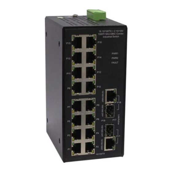
Hardware Description Hardware Description Physical Dimension (W x D x H) is 72mm x 105mm x 152mm (2.8 x 4.1 x 6.0 inches) Front Panel The front panel of the EIR418-2SFP-T is shown below. Manual Documentation Number EIR418-2SFP-T – 0109m www.bb-elec.com www.bb-europe.com... -
Page 7: Top View
Hardware Description Top View The top panel view of the EIR418-2SFP-T is equipped with one terminal block connector that consists of two 12 to 48 VDC power inputs and the fault alarm output. LED Indicators Status Meaning Green Power 1 is active PWR1 No power at input 1 Green... - Page 8 Hardware Description Green Connected to network (Upper LED) Blinking Networking is active (Upper LED) Not connected to network (Upper LED) P1 to P16 Yellow Ethernet port full duplex (Lower LED) Blinking Collision of packets occurs (Lower LED) Ethernet port half duplex or not connected to (Lower LED) network Green...
-
Page 9: Ports
Hardware Description Ports RJ-45 ports: Eight RJ-45 ports auto-sense for 10, 100 Mbps while two ports auto-sense for 10, 100 or 1000 Mbps device connections. The auto MDI/MDIX feature allows connections to switches, workstation and other equipment without changing straight through or crossover cabling. - Page 10 Hardware Description Straight Through Cable Schematic Cross Over Cable Schematic • 2 Gigabit Copper/SFP (Mini-GBIC) combo port: The EIR418-2SFP-T has two auto-detect Giga ports—copper/Fiber combo ports. The Gigabit Copper (10/100/1000T) ports should use Category 5e or above UTP/STP cable for connection.
- Page 11 Hardware Description port will link down. If a 100M SFP transceiver is inserted into the SFP cage the copper combo port will link down regardless of the connection status of the remote device. Manual Documentation Number EIR418-2SFP-T – 0109m www.bb-elec.com www.bb-europe.com...
- Page 12 Hardware Description Manual Documentation Number EIR418-2SFP-T – 0109m www.bb-elec.com www.bb-europe.com...
- Page 13 Hardware Description To connect the transceiver and fiber cable, follow the steps shown below. (Note: SFP modules typically terminate with an LC fiber connector) First, insert the SFP transceiver into the SFP module cage. Notice that the triangle mark is at the bottom of the module.
- Page 14 Hardware Description Second, insert the fiber cable into the transceiver. LC connector to the transceiver To remove the LC connector and SFP transceiver, follow the steps below: First, press the upper side of the LC connector down and pull it out before releasing Remove LC connector Manual Documentation Number EIR418-2SFP-T –...
-
Page 15: Cabling
Hardware Description Second, swivel the metal latch away from the switch and pull the transceiver out. Pull out from the SFP module Cabling Use unshielded twisted-pair (UTP) or shielded twisted-pair (STP) cable. 10Mbps: Use category 3, 4, 5 or greater cable 100Mbps: Use category 5 or greater 1000Mbps: Use category 5e or greater cable Cable distances should be less than 100 meters (328 ft.) long. -
Page 16: Wiring The Fault Alarm Contact
Hardware Description 2. Tighten the wire-clamp screws for prevent the wires from becoming loose. Wiring the Fault Alarm Contact The fault alarm contact is in the middle of the terminal block connector as shown below. If one of the power sources fails a fault will be detected causing the circuit to open. Insert the wires into the fault alarm contact (No. -
Page 17: Mounting Installation
Mounting Installation Mounting Installation DIN-Rail Mounting The DIN rail clip comes screwed on to the switch, from the factory. If the DIN rail clip is not screwed on the switch, please see the following figure to re-attach the DIN-Rail clip. Then follow the steps below to hang the switch onto a DIN rail. - Page 18 Mounting Installation First, insert the top of DIN rail clip onto the piece of the DIN rail track. Then, lightly push the bottom of the switch so it can snap the rest of the way onto the DIN rail track. Check that the switch is held tightly to the DIN rail track.
-
Page 19: Wall Mount Plate Mounting
Mounting Installation • Pulling slowly at the bottom of the switch will bring the switch out so that the switch can now be carefully lifted off the DIN rail track. Wall or Panel Mount Plate Mounting Follow the steps below to mount the switch with the wall mount plate. 1. -
Page 20: Hardware Installation
Hardware Installation Hardware Installation Installation Steps 1. Unpack the switch. 2. Check if the DIN rail clip is screwed on the Industrial switch or not. If the DIN rail clip is not screwed onto switch, please refer to DIN-Rail Mounting section for DIN-Rail installation. -
Page 21: Network Application
Network Application Network Application The diagram below shows a typical switch installation for the EIR418-2SFP-T. Manual Documentation Number EIR418-2SFP-T – 0109m www.bb-elec.com www.bb-europe.com... -
Page 22: Troubles Shooting
Troubleshooting Troubleshooting • Verify that you are using a power supply ranging from 12 to 48VDC. Applying more than 48VDC could cause damage to the switch. • Be sure the proper cable is used in your network. Refer to the Cabling section of this manual for help. -
Page 23: Technical Specification
Technical Specification Technical Specification IEEE 802.3 10Base-T IEEE 802.3u 100Base-TX Standard IEEE 802.3ab 1000Base-T IEEE 802.3z Gigabit fiber IEEE 802.3x Flow Control and Back-pressure Protocol CSMA/CD 14,880 pps for 10Base-T Ethernet port Transfer Rate 148,800 pps for 100Base-TX/FX Fast Ethernet port 1,488,000 pps for Gigabit Fiber Ethernet port MAC address 8K MAC address table... - Page 24 Technical Specification Multi-mode: 50/125um or 62.5/125um Optical cable Single mode: 9/125um Back-plane 7.2Gbps Packet throughput 10.7Mpps at 64bytes ability 12 to 48 VDC Power Supply Redundant power with polarity reverse protection and removable terminal block Power Consumption 9 Watts DIN rail kit for DIN-type cabinet and wall mount ear for Install wall mount install Operating Temp.
- Page 25 Technical Specification CE EN61000-4-11 CE EN61000-4-12 CE EN61000-6-2 CE EN61000-6-4 Safety CE/EN60950-1 IEC60068-2-32 (Free fall) Stability testing IEC60068-2-27 (Shock) IEC60068-2-6 (Vibration) Manual Documentation Number EIR418-2SFP-T – 0109m www.bb-elec.com www.bb-europe.com...
Need help?
Do you have a question about the Elinx EIR418-2SFP-T and is the answer not in the manual?
Questions and answers