Advertisement
Quick Start Guide
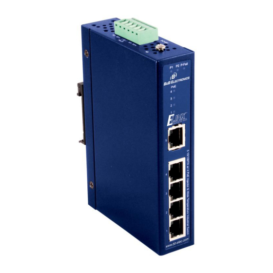
Elinx PoE Ethernet Switch
EIRP305-T
1
Items Included
Ethernet Switch
o
o
CD with Support Manual
This Quick Start Guide
o
Panel Mount Bracket
o
2
Hardware Installation
1.
Select a mounting location and install the
switch onto a piece of DIN rail or use the
included panel mount brackets for wall or
panel mounting
2.
Connect power to the switch
48 VDC
If redundancy is desired be sure to
connect two separate power supplies by
using the two DC inputs on the terminal
blocks
If only one power input is used the Fault
LED will light (this is normal)
3
LED Chart
LED
Description
Green
Power input 1 is active
P1
Off
Power input 1 is inactive
Green
Power input 2 is active
P2
Off
Power input 2 is inactive
Red
Power input 1 or 2 is inactive
Fault
Power input 1 and 2 are both
Off
active, or no power is present
The port is supplying power to
Green
the connected device
FWD
(1 to 4)
No device attached or no power
Off
being supplied
Green
Connected to network
RJ-45
Flashing
Networking is active
Upper LED
Off
Not connected to network
Yellow
Full-duplex link
RJ-45
Flashing
Collision occurs
Lower LED
Off
Half-duplex link or link down
4
Ports
RJ-45 ports: The RJ-45 ports auto-sense for 10 or 100 Mbps
device connections. The auto MDI/MDIX feature allows
connections to switches, workstation and other equipment
without changing straight through or crossover cabling. The
charts below show the cable pin assignments for straight
through and crossover cables.
1. Auto MDI/MDI-x is
MDI-X Cable Pinout
supported. A straight
through or cross-over
cable may be used.
2. 10/100 auto
negotiation and full/half-
duplex are supported.
PoE ports: The PoE ports on this switch follow Alternative A
standards and are limited to 15.4 Watts of power output per
port. Ports 1 thru 4 support the IEEE802.3af standard and
are classified as (PSE) power sourcing equipment, which
means they can be used to power (PD) powered devices.
5
Installation Complete
1. When the network cables are attached and power
is applied, installation is complete.
2. The switch will automatically discover network
devices, populate its MAC address table, and
pass traffic to the appropriate ports.
EIRP305-T-1012qsg
MDI Cable Pinout
Pin
Signal
1
Tx+
2
Tx-
3
Rx+
6
Rx-
Pin
Signal
1
Rx+
2
Rx-
3
Tx+
6
Tx-
Advertisement
Table of Contents

Related Manuals for B&B Electronics Elinx EIRP305-T


Summary of Contents for B&B Electronics Elinx EIRP305-T
- Page 1 EIRP305-T-1012qsg If redundancy is desired be sure to connect two separate power supplies by using the two DC inputs on the terminal Quick Start Guide blocks Ports If only one power input is used the Fault LED will light (this is normal) RJ-45 ports: The RJ-45 ports auto-sense for 10 or 100 Mbps Elinx PoE Ethernet Switch device connections.
- Page 2 X-ON Electronics Largest Supplier of Electrical and Electronic Components Click to view similar products for category: Ethernet Modules Click to view products by manufacturer: B&B Electronics Other Similar products are found below : 1026937 1026932 M38510/00302BCA 70001610 70001634 850-15633 PD-AS-951/12-24 GX-OC1601 1402407 I210T1 I350T4V2 SBL2EX SL170115 GX-OD1612 CPTS-4R4E-R TDKEZW3 I350F2 I350F2BLK I350T2V2 V23993-USB1029A 100-POE4 105FX-ST 105TX-SL SEG305-T 70001992 70001993 708TX 854-19720 I350T4V2BLK I350T2V2BLK I210T1BLK PD-OUT/MBK/S SX-BR- 4600WAN2-US W4S105C X710DA4FHBLK I350T2V2BLK 936714 GX-ID1611 3G8F7-DRM21-E EKI-2525I-BE...
Need help?
Do you have a question about the Elinx EIRP305-T and is the answer not in the manual?
Questions and answers