L-Acoustics KIVA SB15M Rigging Manual
Kiva system
Hide thumbs
Also See for KIVA SB15M:
- Owner's manual (86 pages) ,
- User manual (15 pages) ,
- Rigging manual (12 pages)

Subscribe to Our Youtube Channel
Related Manuals for L-Acoustics KIVA SB15M


Summary of Contents for L-Acoustics KIVA SB15M
- Page 1 KIVA SYSTEM KIVA SB15m RIGGING MANUAL VERSION 1.1 w w w . l - a c o u s t i c s . c o m...
-
Page 2: Safety Instructions
Do not stack the loudspeaker array on unstable ground or surface. If the array is stacked on a structure, platform, or stage, always check that the latter can support the total weight of the array. As a general rule, L-ACOUSTICS ®... -
Page 3: Table Of Contents
® If the product requires repair or for information about the warranty, please contact an approved L-ACOUSTICS ® distributor. The address of the nearest distributor is available on the L-ACOUSTICS web site. -
Page 4: Rigging System Components
An L-ACOUSTICS ® loudspeaker system is the set of components available to form any loudspeaker system based on one of the full-range loudspeaker enclosure afforded by L-ACOUSTICS ® . It includes enclosures, rigging accessories, loudspeaker cables, amplified controllers, and software applications. - Page 5 KIVA SB15m KIBU-SB CLAMP250 SB15MRIG equipped with LOCKTAB KIET (Delivered with the SB15m) SOUNDVISION Main components involved in the KIVA rigging process. w w w . l - a c o u s t i c s . c o m KIVA-SB15 _RM_EN_1.1...
-
Page 6: Mechanical Safety
KIVA SYSTEM KIVA SB15 rigging manual VERSION 1.1 2 MECHANICAL SAFETY Maximum configurations The KIVA system rigging complies with BGV-C1 (2012), DIN 18800 and EN ISO 12100-1 (2004) when the following arrays are deployed. The safe configurations are always compliant with the standards listed before, regardless of the deployment parameters (site angles, inter-enclosure angles, etc.). -
Page 7: System Setup
3 SYSTEM SETUP The KIVA-SB15m rigging system relies on the use of KIBU-SB as an interface between the two enclosures rigging systems. Each side of KIBU-SB is compatible with one enclosure type: KIVA side SB15m side w w w . l - a c o u s t i c s . c o m KIVA-SB15 _RM_EN_1.1... -
Page 8: Ground-Stacking
KIVA SYSTEM KIVA SB15 rigging manual VERSION 1.1 Ground-stacking KIVA Remove the rigging bars from a KIBU-SB. Place the KIBU-SB on the ground with its KIVA side facing up. Attach a KIVA (logo on the left-hand side) to the KIBU-SB. Refer to PROCEDURE B. -
Page 9: Flying
Flying KIVA Place a KIBU-SB on the ground with its KIVA side facing up. Attach a KIVA enclosure to the KIBU-SB. Refer to PROCEDURE B. Turn the KIVA/KIBU-SB assembly upside down. Attach a bow shackle WLL 1 t or a CLAMP250 on the KIBU-SB. Refer to PROCEDURE B. -
Page 10: Pole-Mounting
KIVA SYSTEM KIVA SB15 rigging manual VERSION 1.1 Pole-mounting KIVA + SB15m Place a SB15m (logo down) on the ground. If two KIVA are required, place one enclosure on the ground (logo on the left-hand side) and attach a second enclosure to it. Refer to PROCEDURE B. -
Page 11: Subset Procedures
4 SUBSET PROCEDURES PROCEDURE A Attaching the SB15m to a second element Remove the bar from its storage location. From the front of the array, slide the bar into adjacent rigging rails. Secure the bar with the locking tab. Accurately position the bar by pushing it into place. b. -
Page 12: Procedure B Attaching Kiva To A Another Element
KIVA SYSTEM KIVA SB15 rigging manual VERSION 1.1 PROCEDURE B Attaching KIVA to a another element The rigging procedure used to attach a KIVA enclosure to another KIVA enclosure and to KIBU-SB is similar. The main difference lies in: the possibility to choose front or rear position of the enclosure on the bumper (see next page), ... - Page 13 If you are attaching a KIVA enclosure to a KIBU-SB, refer to the SOUNDVISION modeling to identify the position (rear, front) that corresponds to the targeted site angle. 2. Attach the two linking points at the front of the enclosure to the two linking points of the other element (enclosure or KIBU-SB).
- Page 14 KIVA SYSTEM KIVA SB15 rigging manual VERSION 1.1 3.a. Releasing the angulation arm. Attaching the angulation arm of a KIVA to 3.b. Attaching the angulation arm of a KIVA to KIBU-SB. KIVA. w w w . l - a c o u s t i c s . c o m KIVA-SB15 _RM_EN_1.1...
-
Page 15: Procedure C Attaching A Shackle Or Clamp250
PROCEDURE C Attaching a shackle or CLAMP250 Refer to SOUNDVISION modeling to identify the hole number that corresponds to the targeted tilt angle. KIBU-SB hole numbering on the side of the SB15m KIBU-SB hole numbering on the side of the KIVA 2. -
Page 16: Procedure D Attaching Kiet To Kiva
KIVA SYSTEM KIVA SB15 rigging manual VERSION 1.1 PROCEDURE D Attaching KIET to KIVA The site angle of a pole-mounted KIVA enclosure is defined by its angle with the KIET. Refer to Figure 2 to choose the hole corresponding to the targeted site angle. Figure 2 Angulation arm holes EQUIPMENT Electric screwdriver with torque selector. - Page 17 PROCEDURE D Assembling the KIET and its pole adapter. Attaching the KIET and the enclosure. Securing the enclosure angulation arm on the KIET. w w w . l - a c o u s t i c s . c o m KIVA-SB15 _RM_EN_1.1...
-
Page 18: Appendix Ainstalling The Lap-Teq Inclinometer
INSTALLING THE LAP-TEQ INCLINOMETER ® The KIBU-SB is equipped with a laser support plate for the installation of the TEQSAS LAP-TEQ inclinometer. The LAP-TEQ is a remote control device which is part of the L-ACOUSTICS ® TECH TOOLCASE. Equipment Electric screwdriver with torque selector. -
Page 19: Appendix Bspecifications
APPENDIX B SPECIFICATIONS KIVA Description 2-way passive enclosure, amplified by LA4 or LA8 Usable bandwidth (-10 dB) 80 Hz - 20 kHz ([KIVA] preset) Maximum SPL 130 dB ([KIVA] preset) Horizontal: 100° (from 500 Hz) Coverage angle (-6 dB) Vertical: depends on the number of elements and array curvature LF: 2 ... -
Page 20: Sb15M
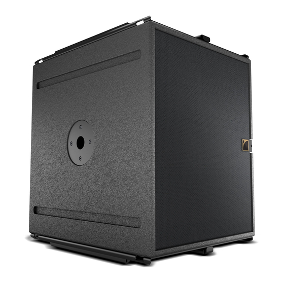
KIVA SYSTEM KIVA SB15 rigging manual VERSION 1.1 SB15m Description Subwoofer enclosure, amplified by LA4 or LA8 Low frequency limit (‑10 dB) 40 Hz ([SB15_100] preset) Maximum SPL 135 dB ([SB15_100] preset) RMS power handling 600 W 1 15" weather-resistant, bass-reflex Transducer Nominal impedance 8 Ω...
Need help?
Do you have a question about the KIVA SB15M and is the answer not in the manual?
Questions and answers