Keysight U1231A User Manual
Handheld digital multimeter
Hide thumbs
Also See for U1231A:
- Quick start manual (177 pages) ,
- User manual (136 pages) ,
- Quick start manual (18 pages)
Table of Contents
Advertisement
Quick Links
Advertisement
Table of Contents

Related Manuals for Keysight U1231A


Summary of Contents for Keysight U1231A
-
Page 1: Digital Multimeter
Keysight U1231A, U1232A, and U1233A Handheld Digital Multimeter User’s Guide... - Page 3 Keysight U1231A, U1232A, and U1233A User’s Guide...
-
Page 4: Safety Information
FAR 27.401 or DFAR 227.7103-5 (c), as applicable in any Do not proceed beyond a WARNING technical data. notice until the indicated conditions are fully understood and met. Keysight U1231A, U1232A, and U1233A User’s Guide... -
Page 5: Safety Symbols
Warning or Caution information) Equipment protected throughout by double AC (Alternating current or voltage) insulation or reinforced insulation CAT III Earth (ground) terminal Category III 600 V overvoltage protection 600 V Keysight U1231A, U1232A, and U1233A User’s Guide... -
Page 6: Safety Considerations
Failure to comply with these precautions or with specific warnings elsewhere in this manual violates safety standards for design, manufacture, and intended use of the instrument. Keysight Technologies assumes no liability for the customer’s failure to comply with these requirements. - Page 7 – Do not operate the meter with the battery cover or portions of the cover removed or loosened. – To avoid false readings, which may lead to possible electric shock or personal injury, replace the battery as soon as the low battery indicator appears and flashes. Keysight U1231A, U1232A, and U1233A User’s Guide...
-
Page 8: Measurement Category
Measurement Category The Keysight U1231A, U1232A, and U1233A has a safety rating of CAT III 600V. Measurement CAT I Measurements performed on circuits not directly connected to the AC mains. Examples are measurements on circuits not derived from the AC mains and specially protected (internal) mains-derived circuits. -
Page 9: Environmental Conditions
Storage temperature –40 °C to 60 °C Altitude Up to 2000 meters Pollution degree The U1231A/U1232A/U1233A Handheld Digital Multimeter complies with the NOTE following safety and EMC requirements: – IEC 61010-1:2010/EN 61010-1:2010 – USA: UL 61010-1 (3rd Edition) – Canada: CSA C22.2 No. 61010-1:2012... -
Page 10: Regulatory Markings
The CSA mark is a registered trademark of substance elements are expected to leak the Canadian Standards Association. or deteriorate during normal use. Forty years is the expected useful life of the product. Keysight U1231A, U1232A, and U1233A User’s Guide... -
Page 11: Waste Electrical And Electronic Equipment (Weee) Directive 2002/96/Ec
To return this unwanted instrument, contact your nearest Keysight Service Center, or visit http://about.keysight.com/en/companyinfo/environment/takeback.shtml for more information. Sales and Technical Support To contact Keysight for sales and technical support, refer to the support links on the following Keysight websites: – www.keysight.com/find/u1230dmm (product-specific information and support, software and documentation updates) –... - Page 12 THIS PAGE HAS BEEN INTENTIONALLY LEFT BLANK. Keysight U1231A, U1232A, and U1233A User’s Guide...
-
Page 13: Table Of Contents
..........41 Keysight U1231A, U1232A, and U1233A User’s Guide... - Page 14 ........104 Keysight U1231A, U1232A, and U1233A User’s Guide...
- Page 15 Changing the temperature unit ......119 Characteristics and Specifications Keysight U1231A, U1232A, and U1233A User’s Guide...
- Page 16 THIS PAGE HAS BEEN INTENTIONALLY LEFT BLANK. Keysight U1231A, U1232A, and U1233A User’s Guide...
- Page 17 Figure 2-22 DC current display ......78 Keysight U1231A, U1232A, and U1233A User’s Guide...
- Page 18 ... 119 Figure 4-17 Changing the temperature unit ....120 Keysight U1231A, U1232A, and U1233A User’s Guide...
- Page 19 .....100 Table 4-2 Setup menu item descriptions ....102 Keysight U1231A, U1232A, and U1233A User’s Guide...
- Page 20 THIS PAGE HAS BEEN INTENTIONALLY LEFT BLANK. Keysight U1231A, U1232A, and U1233A User’s Guide...
-
Page 21: Introduction
Keysight U1231A, U1232A, and U1233A Handheld Digital Multimeter User’s Guide Introduction About This Manual Preparing Your Multimeter Your Multimeter in Brief Cleaning Your Multimeter This chapter teaches you how to set up your multimeter for the first time. An introduction to all the features of the multimeter is also given. -
Page 22: About This Manual
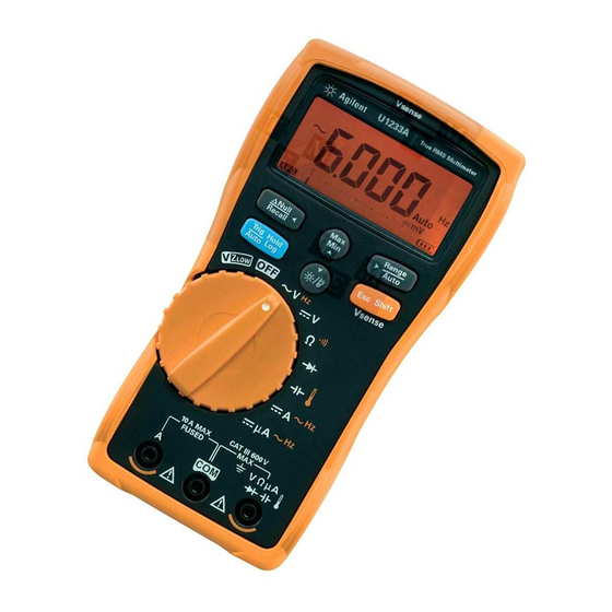
Introduction About This Manual The descriptions and instructions in this manual apply to the Keysight U1231A, U1232A, and U1233A handheld digital multimeters (hereafter referred to as the multimeter). The model U1233A appears in all illustrations. Documentation map The following manuals and software are available for your multimeter. For the very latest version, please visit our website at: http://www.keysight.com/find/... -
Page 23: Preparing Your Multimeter
U1231A/U1232A/U1233A Quick Start Guide. 3 For any question or problems, refer to the Keysight contact numbers on the back of this manual. Installing the batteries Your multimeter is powered by four 1.5 V AAA alkaline batteries (included with the... -
Page 24: Figure 1-1 Installing The Batteries
Figure 1-1 Installing the batteries The battery level indicator in the lower right-hand corner of the display indicates the relative condition of the batteries. Table 1-1 describes the various battery levels the indicator represents. Keysight U1231A, U1232A, and U1233A User’s Guide... -
Page 25: Table 1-1 Table
To avoid instruments being damage from battery leakage: CAUTION – Always remove dead batteries immediately. – Always remove the batteries and store them separately if the multimeter is not going to be used for a long period. Keysight U1231A, U1232A, and U1233A User’s Guide... -
Page 26: Turning On Your Multimeter
To change the timeout period or completely disable the automatic power-off, NOTE refer to “Changing the auto power-off (APO) timeout” on page 108. Keysight U1231A, U1232A, and U1233A User’s Guide... -
Page 27: Enabling The Backlight
VISION ADVISORY CLAIM CAUTION The LED light source is safe for normal usage. However, staring directly into the LED light source is not recommended as prolonged direct exposure may be harmful to the eyes. Keysight U1231A, U1232A, and U1233A User’s Guide... -
Page 28: Power-On Options
HELP, dEMo, or flashlight mode. Press and hold for more than 1 second to toggle the flashlight on or off (for any of the modes — HELP, dEMo, or flashlight mode). Keysight U1231A, U1232A, and U1233A User’s Guide... -
Page 29: Selecting The Range
Each additional press of sets the multimeter to the next higher range, unless it is already in the highest range, at which point the range switches to the lowest range. Keysight U1231A, U1232A, and U1233A User’s Guide... -
Page 30: Alerts And Warnings During Measurement
Hazardous voltage indication The multimeter will also display the hazardous voltage ( ) symbol as an early precaution when the measured voltage is equal to or greater than 30 V in all voltage measurement modes. Keysight U1231A, U1232A, and U1233A User’s Guide... -
Page 31: Adjusting The Tilt Stand
Connecting the IR-USB cable You can use the IR communication link (IR communication port, located at the rear panel) and the Keysight GUI Data Logger software to control your multimeter remotely, perform data logging operations, and transfer the contents of your multimeter’s memory to a PC. -
Page 32: Figure 1-4 Keysight Gui Data Logger Software
Keysight GUI Data Logger match the communication settings mentioned in this note. Refer to the Keysight GUI Data Logger Software Help and Quick Start Guide for more information on the IR communication link and the Keysight GUI Data Logger software. -
Page 33: Power-On Options
1 second to toggle the flashlight on or off (for any of the modes — HELP, dEMo, or flashlight mode). – Press and hold for more than 1 second to exit this mode. Keysight U1231A, U1232A, and U1233A User’s Guide... -
Page 34: Your Multimeter In Brief
Introduction Your Multimeter in Brief Dimensions Front view 86 mm Figure 1-5 Wid th dimension Keysight U1231A, U1232A, and U1233A User’s Guide... -
Page 35: Figure 1-6 Height And Depth Dimensions
Introduction Rear and side view 52 mm 169 mm Figure 1-6 Height and depth dimensions Keysight U1231A, U1232A, and U1233A User’s Guide... -
Page 36: Overview
Front panel Table 1-3 Front panel parts Legend Description Learn more on: Display screen page 43 Keypad page 41 Terminals page 46 Voltage presence indicator (U1233A only) page 86 Rotary switch page 38 Keysight U1231A, U1232A, and U1233A User’s Guide... -
Page 37: Figure 1-8 Rear Panel
Figure 1-8 Rear panel Table 1-4 Rear panel parts Legend Description Learn more on: IR communication port page 31 Tilt stand page 31 Battery and fuse access cover page 23 Flashlight page 27 Keysight U1231A, U1232A, and U1233A User’s Guide... -
Page 38: Rotary Switch
Remove the test leads from the measuring source or target before changing WARNING the rotary switch position. Each position of the U1231A, U1232A, and U1233A rotary switch (shown in Figure 1-7) is described in Table 1-5. - Page 39 – Resistance measurement (Ω) Diode test (V) page 65 U1233A: Capacitance U1233A: Temperature measurement (F) measurement U1232A: Capacitance U1232A: Auxiliary temperature page 69 measurement (F) measurement page 71 U1231A: Capacitance U1231A: N/A measurement (F) Keysight U1231A, U1232A, and U1233A User’s Guide...
-
Page 40: Table 1-5 Table
[a] The open continuity test option must be enabled through the Setup menu. To learn more, see “Enable open continuity test by default” page 119. The open continuity test option is disabled by default. Keysight U1231A, U1232A, and U1233A User’s Guide... -
Page 41: Keypad
(Max), minimum (Min), average (Avg), or mode. present (MaxMinAvg) readings. – Press to restart the recording session. Sets a manual range and disables autoranging. Enables autoranging. page 29 – Press again to cycle through each available measurement range. Keysight U1231A, U1232A, and U1233A User’s Guide... - Page 42 — if available). page 86 voltage presence indicator. Press for more Press again to switch back to the regular than 1 second to exit this mode. measurement function. Keysight U1231A, U1232A, and U1233A User’s Guide...
-
Page 43: Display Screen
– Capacitor is discharging (during capacitance measurement) page 61 – Short continuity test Calibration enabled Scale transfer enabled page 96 Smooth mode enabled page 105 APO (Auto Power-Off) enabled page 26 Trigger hold enabled page 92 Keysight U1231A, U1232A, and U1233A User’s Guide... -
Page 44: Figure 2-21 Temperature Measurement Without Ambient
Diode test selected page 65 Measurement range selected page 29 Audible continuity test selected page 61 Hold-Log recall mode enabled page 94 Battery capacity indication page 25 Overload (the reading exceeds the display range) Keysight U1231A, U1232A, and U1233A User’s Guide... -
Page 45: Table 1-9 Table
Farad units for capacitance measurement Ω, kΩ, MΩ Ohm units for resistance measurement MHz, kHz, Hz Hertz units for frequency measurement °C Degree Celsius, unit for temperature measurement °F Degree Fahrenheit, unit for temperature measurement Keysight U1231A, U1232A, and U1233A User’s Guide... -
Page 46: Input Terminals
Ensure that the probe accessories are connected to the correct input WARNING terminals for the selected measurement function before starting any measurement. [1] The analog bar graph display update rate is approximately 33 times/second for DC voltage, current, and resistance measurements. Keysight U1231A, U1232A, and U1233A User’s Guide... -
Page 47: U1231A Terminal Connections For Different Measuring Functions
Introduction To avoid damaging this device, do not exceed the rated input limit. CAUTION Table 1-10 U1231A terminal connections for different measuring functions Rotary switch position Input terminals Overload protection U1231A 600 Vrms 600 Vrms for short circuit <0.3 A... -
Page 48: U1232A And U1233A Terminal Connections
Table 1-11 U1232A and U1233A terminal connections for different measuring functions Rotary switch position Input terminals Overload protection U1233A U1232A 600 Vrms 600 Vrms for short circuit <0.3 A 11 A/1000 V, fast-acting fuse Keysight U1231A, U1232A, and U1233A User’s Guide... -
Page 49: Cleaning Your Multimeter
2 Turn the multimeter over and shake out any dirt that may have accumulated in the terminals. Wipe the case with a damp cloth and mild detergent — do not use abrasives or solvents. Wipe the contacts in each terminal with a clean swab dipped in alcohol. Keysight U1231A, U1232A, and U1233A User’s Guide... - Page 50 Introduction THIS PAGE HAS BEEN INTENTIONALLY LEFT BLANK. Keysight U1231A, U1232A, and U1233A User’s Guide...
- Page 51 Keysight U1231A, U1232A, and U1233A Handheld Digital Multimeter User’s Guide Making Measurements Measuring AC Voltage Measuring DC Voltage Using VZLOW for Voltage Measurements Measuring Resistance Testing for Continuity Testing Diodes Measuring Capacitance Measuring Temperature Measuring AC or DC Current Measuring Frequency...
-
Page 52: Making Measurements
(with no DC offset) such as square waves, triangle waves, and staircase waves. Figure 2-1 AC voltage display Press to measure the frequency of the AC voltage source. See “Measuring NOTE Frequency” on page 82 to learn more. Keysight U1231A, U1232A, and U1233A User’s Guide... -
Page 53: Figure 2-2 Measuring Ac Voltage
Making Measurements Figure 2-2 Measuring AC voltage Keysight U1231A, U1232A, and U1233A User’s Guide... -
Page 54: Measuring Dc Voltage
You can choose to set the multimeter to measure AC or DC mV at the rotary positions shown below. – U1233A: – U1232A: – U1231A: Use the Setup menu to enable AC/DC mV measurements. See “Enable the AC/DC mV measurement” on page 118 to learn more. Keysight U1231A, U1232A, and U1233A User’s Guide... -
Page 55: Figure 2-4 Measuring Dc Voltage
Making Measurements Figure 2-4 Measuring DC voltage Keysight U1231A, U1232A, and U1233A User’s Guide... -
Page 56: Using Vz Low For Voltage Measurements
Figure 2-5 voltage display During VZ measurements, the multimeter’s range is locked to 600 V. NOTE The analog bar graph represents the AC+DC voltage value combined. Keysight U1231A, U1232A, and U1233A User’s Guide... -
Page 57: Figure 2-6 Measuring Vz Low Voltage
(AC V or DC V). Press again to exchange the AC and DC voltage indication on the primary display. Pressing for the third time will restart the auto identification of the signal. See Figure 2-7 to learn more. Keysight U1231A, U1232A, and U1233A User’s Guide... -
Page 58: Figure 2-7 Vz Low Auto Identification Flow
Use this simple and quick test to determine if a battery has enough voltage capacity to support regular activities. Prolonged use of the VZ function will consume the capacity of the NOTE battery-under-test. Keysight U1231A, U1232A, and U1233A User’s Guide... -
Page 59: Measuring Resistance
To remove lead resistance from the measurement, hold the test lead tips together and press . Now the resistance at the probe tips will be subtracted from all future display readings. Keysight U1231A, U1232A, and U1233A User’s Guide... -
Page 60: Figure 2-9 Measuring Resistance
– The resistance function can produce enough voltage to forward-bias silicon diodes or transistor junctions, causing them to conduct. If this is suspected, press to apply a lower current in the next higher range. Figure 2-9 Measuring resistance Keysight U1231A, U1232A, and U1233A User’s Guide... -
Page 61: Testing For Continuity
<131 ± 60 kΩ 60.00 MΩ <131 ± 60 kΩ Press to switch between resistance measurement, short continuity test ( ), or open continuity test ( ). See Figure 2-10 to learn more. Keysight U1231A, U1232A, and U1233A User’s Guide... -
Page 62: Figure 2-10 Continuity Test Flow
Circuit open P ress to switch to the open continuity test O pen detected, beeper sounds Circuit complete P ress to switch to the resistance measurement Figure 2-10 Continuity test flow Keysight U1231A, U1232A, and U1233A User’s Guide... - Page 63 – You can enable or disable the audible and visual alert via the Setup menu. “Changing the continuity test alerts” on page 113 for more information on the audible and visual alert options. Keysight U1231A, U1232A, and U1233A User’s Guide...
-
Page 64: Figure 2-11 Testing For Continuity
Making Measurements Figure 2-11 Testing for continuity Keysight U1231A, U1232A, and U1233A User’s Guide... -
Page 65: Testing Diodes
2.1 V. The forward bias of a typical diode is within the range of 0.3 V to 0.8 V; however, the reading can vary depending on the resistance of other pathways between the probe tips. Keysight U1231A, U1232A, and U1233A User’s Guide... -
Page 66: Figure 2-13 Open Diode Display
– A diode is considered open if the multimeter displays in both forward and reverse bias modes. Figure 2-13 Open diode display Keysight U1231A, U1232A, and U1233A User’s Guide... -
Page 67: Figure 2-14 Testing Forward Bias Diode
Making Measurements Figure 2-14 Testing forward bias diode Keysight U1231A, U1232A, and U1233A User’s Guide... -
Page 68: Figure 2-15 Testing Reverse Bias Diode
Making Measurements Figure 2-15 Testing reverse bias diode Keysight U1231A, U1232A, and U1233A User’s Guide... -
Page 69: Measuring Capacitance
– For measuring capacitance values greater than 1000 μF, discharge the capacitor first, then select a suitable range for measurement. This will speed up the measurement time and also ensures that the correct capacitance value is obtained. Keysight U1231A, U1232A, and U1233A User’s Guide... -
Page 70: Figure 2-17 Measuring Capacitance
Making Measurements Figure 2-17 Measuring capacitance Keysight U1231A, U1232A, and U1233A User’s Guide... -
Page 71: Measuring Temperature
U1186A (purchased separately) is recommended. It is only compatible with the U1233A. – For auxiliary temperature measurement on the U1231A and U1232A, a temperature module such as the U1586B (purchased separately) is required. – The approximate ambient temperature (cold-junction compensation) is shown on the display when you have an open thermocouple. -
Page 72: Figure 2-18 Temperature Display
The option to toggle between °C and °F is only available for the U1233A model. NOTE Always set the temperature unit display per the official requirements and in CAUTION compliance with the national laws of your region. Keysight U1231A, U1232A, and U1233A User’s Guide... -
Page 73: Figure 2-19 Measuring The Surface Temperature
Making Measurements Figure 2-19 Measuring the surface temperature Keysight U1231A, U1232A, and U1233A User’s Guide... -
Page 74: Figure 2-20 Using The Auxillary Temperature Measurement Function (Only Applicable For The U1231A And U1232A Models)
Making Measurements Figure 2-20 Using the Auxillary Temperature measurement function (Only applicable for the U1231A and U1232A models) Keysight U1231A, U1232A, and U1233A User’s Guide... - Page 75 Available options: – °C - Temperature measured in °C only. – °C°F - During temperature measurements, press to switch between °C and °F. Keysight U1231A, U1232A, and U1233A User’s Guide...
- Page 76 3 After a constant reading is obtained, press to set the reading as the relative reference temperature. 4 Touch the surface to be measured with the thermocouple probe and read the display. Figure 2-21 Temperature measurement without ambient compensation Keysight U1231A, U1232A, and U1233A User’s Guide...
-
Page 77: Measuring Ac Or Dc Current
600 μA. – Press to cycle between DC current measurement, AC current measurement, or to measure the frequency of the AC current source. See “Measuring Frequency” on page 82 to learn more. Keysight U1231A, U1232A, and U1233A User’s Guide... -
Page 78: Figure 2-22 Dc Current Display
This happens because the resistance through the multimeter's current terminals is very low, resulting in a short circuit. Keysight U1231A, U1232A, and U1233A User’s Guide... -
Page 79: Figure 2-24 Measuring Dc/Ac Current (Up To A)
Making Measurements Figure 2-24 Measuring DC/AC current (up to A) Keysight U1231A, U1232A, and U1233A User’s Guide... -
Page 80: Figure 2-25 Measuring Ac/Dc Current (Up To Μa)
Making Measurements Figure 2-25 Measuring AC/DC current (up to μA) Keysight U1231A, U1232A, and U1233A User’s Guide... - Page 81 1 Set up your multimeter to measure μA measurements as shown in Figure 2-25. 2 Connect the multimeter between the flame sensor probe (COM terminal) and the ignition control module (mA terminal). 3 Probe the test points and read the display. Keysight U1231A, U1232A, and U1233A User’s Guide...
-
Page 82: Measuring Frequency
Figure 2-26. – The multimeter measures the frequency of a voltage or current signal by counting the number of times the signal crosses a threshold level within a specified period of time. Keysight U1231A, U1232A, and U1233A User’s Guide... -
Page 83: Figure 2-26 Frequency Definition
– If a reading shows as 0 Hz or is unstable, the input signal may be below or near the trigger level. You can usually correct these problems by manually selecting a lower input range, which increases the sensitivity of the multimeter. Keysight U1231A, U1232A, and U1233A User’s Guide... -
Page 84: Figure 2-28 Measuring Frequency
Distortion can cause multiple triggerings of the frequency counter. Selecting a higher voltage range might solve this problem by decreasing the sensitivity of the multimeter. In general, the lowest frequency displayed is the correct one. Figure 2-28 Measuring frequency Keysight U1231A, U1232A, and U1233A User’s Guide... -
Page 85: Multimeter Features
Keysight U1231A, U1232A, and U1233A Handheld Digital Multimeter User’s Guide Multimeter Features Detecting AC Voltage Presence (Vsense) Making Relative Measurements (Null) Capturing Maximum and Minimum Values (MaxMin) Freezing the Display (Trig Hold-Log and Auto Hold-Log) Recalling Previously Recorded Readings (Recall) Making Scale Transfers (Scale) The chapter describes the additional features available in your multimeter. -
Page 86: Detecting Ac Voltage Presence (Vsense)
AC voltage presence. No resolution and accuracy of voltage measurement will be d isplayed in this mode. Press to toggle the Vsense detector’s sensitivity between (high sensitivity) or (low sensitivity). Keysight U1231A, U1232A, and U1233A User’s Guide... -
Page 87: Figure 3-1 Detecting Voltage Presence
AC voltage is recessed within the connector itself. Figure 3-1 Detecting voltage presence Press and hold for more than 1 second to disable the Vsense function. Keysight U1231A, U1232A, and U1233A User’s Guide... -
Page 88: Making Relative Measurements (Null)
For any measurement function, you can directly measure and store the null value by pressing with the test leads open (nulls the test lead capacitance), shorted (nulls the test lead resistance), or across a desired null value circuit. Keysight U1231A, U1232A, and U1233A User’s Guide... -
Page 89: Figure 3-3 Null Operation
P ress to enable the Null function Display returns to P ress to view the stored null value normal after 3 seconds P ress again to disable the Null function Figure 3-3 Null operation Keysight U1231A, U1232A, and U1233A User’s Guide... -
Page 90: Capturing Maximum And Minimum Values (Maxmin)
Max, Min, Avg, or present (MaxMinAvg) input values. 3 Press to restart the recording session. 4 Press for more than 1 second to disable the MaxMin function. Figure 3-4 MaxMin display Keysight U1231A, U1232A, and U1233A User’s Guide... - Page 91 The true average value displayed is the arithmetic mean of all readings taken since the start of recording. The average reading is useful for smoothing out unstable inputs, calculating power consumption, or estimating the percentage of time a circuit is active. Keysight U1231A, U1232A, and U1233A User’s Guide...
-
Page 92: Freezing The Display (Trig Hold-Log And Auto Hold-Log)
NOTE Press and hold for more than 1 second to exit this mode. Keysight U1231A, U1232A, and U1233A User’s Guide... -
Page 93: Auto Hold-Log Operation
Press and hold until the multimeter restarts. If the reading value is unable to reach a stable state (when exceeding the preset NOTE variation), the reading value will not be updated. Keysight U1231A, U1232A, and U1233A User’s Guide... -
Page 94: Recalling Previously Recorded Readings (Recall)
1 second to enter the Recall menu. The last recorded reading is shown on the display. The analog bar graph is used to indicate the record index. Figure 3-7 View display If nothing has been recorded, is displayed instead. Keysight U1231A, U1232A, and U1233A User’s Guide... -
Page 95: Figure 3-8 Empty View Display
1 second until is shown on the display. 3 All data entries stored in the multimeter’s nonvolatile memory will be erased. 3 Press for more than 1 second to exit the Recall menu. Keysight U1231A, U1232A, and U1233A User’s Guide... -
Page 96: Making Scale Transfers (Scale)
[c] Dependent on temperature unit setup. If °C or °C°F is selected, 1 °C/mV is shown as the selected scale item. If °F or °F°C is selected, 1 °F/mV is shown as the selected scale item instead. Keysight U1231A, U1232A, and U1233A User’s Guide... - Page 97 3 You can only change the selected Scale item from the Setup menu. See “Changing the scale conversion value” on page 116 to learn more. 4 The Scale operation is enabled until the multimeter’s power is cycled. Keysight U1231A, U1232A, and U1233A User’s Guide...
- Page 98 Multimeter Features THIS PAGE HAS BEEN INTENTIONALLY LEFT BLANK. Keysight U1231A, U1232A, and U1233A User’s Guide...
-
Page 99: Multimeter Setup Options
Keysight U1231A, U1232A, and U1233A Handheld Digital Multimeter User’s Guide Multimeter Setup Options Using the Setup Menu Setup Menu Summary Setup Menu Items The chapter describes how to change the preset features of your multimeter. -
Page 100: Using The Setup Menu
(most right digit). Next, use the to move the cursor to the other numerical digit(s). – Press to move the cursor to the left, and – Press to move the cursor to the right. Keysight U1231A, U1232A, and U1233A User’s Guide... - Page 101 – Press to decrement the digit. When you have completed your changes, save the new numerical value by pressing . (Or alternatively, if you wish to discard the changes you made, press Keysight U1231A, U1232A, and U1233A User’s Guide...
-
Page 102: Setup Menu Summary
Lo, 02, 03, ME, 05, 06, or Hi Default is Hi. page 112 Set the minimum measurement frequency (0.5 Hz or 5.0 Hz). page 82 (0.5 or 5.0) Hz Default is 0.5 Hz. page 113 Keysight U1231A, U1232A, and U1233A User’s Guide... -
Page 103: Table
Enable or disable the open continuity test. Default is disabled page 61 oPn.d or oPn.E (oPn.d). page 119 Set the multimeter’s temperature unit (Celsius, Celsius/ page 71 °C, °C°F, °F, or °F°C Fahrenheit, Fahrenheit, Fahrenheit/Celsius). Default is °C page 119 (Celsius). Keysight U1231A, U1232A, and U1233A User’s Guide... -
Page 104: Setup Menu Items
Defaul t setting AutoHold (001 to 999) counts 50 counts Press P ress P ress Press Press Press Press Press P ress P ress Press P ress Figure 4-1 Changing the variation count Keysight U1231A, U1232A, and U1233A User’s Guide... -
Page 105: Enabling And Changing The Smooth Refresh Rate
P ress P ress Press P ress P ress P ress P ress P ress P ress Press P ress P ress Figure 4-2 Enabling and changing the Smooth refresh rate Keysight U1231A, U1232A, and U1233A User’s Guide... -
Page 106: Enabling And Changing The Voltage Alert Level
(1 to 660).(d or E) V 030.d V (disabled) Press P ress P ress P ress Press Press Press P ress Press P ress Press Press Figure 4-3 Enabling and changing the voltage alert level Keysight U1231A, U1232A, and U1233A User’s Guide... -
Page 107: Changing The Beep Frequency
Parameter Range Defaul t setting (3.2, 3.4, 3.8, 4.2) kHz or –.– (off) 3.8 kHz P ress P ress P ress P ress Press Press Press Press Figure 4-4 Changing the beep frequency Keysight U1231A, U1232A, and U1233A User’s Guide... -
Page 108: Changing The Auto Power-Off (Apo) Timeout
(01 to 99).(d or E) minutes (15.E) minutes (enabled) Press P ress Press Press Press P ress Press P ress P ress P ress Press Press Figure 4-5 Changing the auto power-off timeout Keysight U1231A, U1232A, and U1233A User’s Guide... -
Page 109: Changing The Lcd Backlight Timeout
(01 to 99).(d or E) seconds (15.E) seconds (enabled) P ress Press P ress P ress P ress P ress P ress P ress Press P ress P ress P ress Figure 4-6 Changing the LCD backlight timeout Keysight U1231A, U1232A, and U1233A User’s Guide... -
Page 110: Adjusting The Lcd Backlight Intensity
ME, 05, 06, or Hi). Parameter Range Defaul t setting Lo, 02, 03, ME, 05, 06, or Hi P ress Press P ress Press P ress Press Figure 4-7 Changing the LCD backlight intensity Keysight U1231A, U1232A, and U1233A User’s Guide... -
Page 111: Enabling The Led Flashlight Timeout
(01 to 99).(d or E) seconds (15.d) seconds (disabled) P ress Press P ress P ress P ress P ress P ress P ress Press P ress P ress P ress Figure 4-8 Changing the LED flashlight timeout Keysight U1231A, U1232A, and U1233A User’s Guide... -
Page 112: Adjusting The Led Flashlight Intensity
ME, 05, 06, or Hi). Parameter Range Defaul t setting Lo, 02, 03, ME, 05, 06, or Hi Press P ress Press P ress Press P ress Figure 4-9 Changing the LED flashlight intensity Keysight U1231A, U1232A, and U1233A User’s Guide... -
Page 113: Changing The Minimum Measurable Frequency
61). You can set the beeper to sound and the backlight to flash as a continuity indication whether the circuit-under-test is less than (short) or more than or equal to (open) the threshold resistance. Keysight U1231A, U1232A, and U1233A User’s Guide... -
Page 114: Figure 4-11 Changing The Continuity Test Alerts
Defaul t setting bE.bL, – –.bL, to.nE, – –.– –, or bE.– – bE.bL P ress Press P ress Press P ress Press P ress Press Figure 4-11 Changing the continuity test alerts Keysight U1231A, U1232A, and U1233A User’s Guide... -
Page 115: Changing The Power-On Greeting Tone
(off). Parameter Range Defaul t setting m(elody) MELo, USEr, bEEE, or oFF MELo P ress P ress P ress P ress Press Press Figure 4-12 Changing the power-on greeting tone Keysight U1231A, U1232A, and U1233A User’s Guide... -
Page 116: Resetting The Setup Items
1000 °C(°F)/V, 1000 V/V, 100 A/V, 10 A/V, 1 A/V, or 0.1 A/V). Parameter Range Defaul t setting Scale 1000 A/V, 1000 °C(°F)/V, 1000 V/V, 100 A/V, 10 A/V, 1 A/V, 1000 A/V or 0.1 A/V Keysight U1231A, U1232A, and U1233A User’s Guide... -
Page 117: Figure 4-14 Changing The Scale Conversion Value
P ress P ress P ress P ress P ress Press P ress P ress P ress Press P ress P ress P ress P ress Figure 4-14 Changing the scale conversion value Keysight U1231A, U1232A, and U1233A User’s Guide... -
Page 118: Enable The Ac/Dc Mv Measurement
– For AC/DC mV measurements, the measurement range is fixed at 600 mV and the input impedance is typically 10 MΩ. – Press to switch between DC mV, AC mV, and frequency measurements. P ress Press Figure 4-15 Enable the AC/DC mV measurement Keysight U1231A, U1232A, and U1233A User’s Guide... -
Page 119: Enable Open Continuity Test By Default
– Celsius only: Temperature measured in °C. – Celsius/Fahrenheit: During temperature measurements, press to switch between °C and °F. – Fahrenheit only: Temperature measured in °F. – Fahrenheit/Celsius: During temperature measurements, press to switch between °F and °C. Keysight U1231A, U1232A, and U1233A User’s Guide... -
Page 120: Figure 4-17 Changing The Temperature Unit
Always set the temperature unit display per the official requirements and in CAUTION compliance with the national laws of your region. P ress Press P ress Press P ress Press Figure 4-17 Changing the temperature unit Keysight U1231A, U1232A, and U1233A User’s Guide... -
Page 121: Specifications
Keysight U1231A, U1232A, and U1233A Handheld Digital Multimeter User’s Guide Characteristics and Specifications For the characteristics and specifications of the U1231A, U1232A, and U1233A Handheld Digital Multimeter, refer to the datasheet at http://literature.cdn.keysight.com/litweb/pdf/5990-7550EN.pdf. - Page 122 Characteristics and Specifications THIS PAGE HAS BEEN INTENTIONALLY LEFT BLANK. Keysight U1231A, U1232A, and U1233A User’s Guide...
- Page 123 This information is subject to change without notice. Always refer to the English version at the Keysight website for the latest revision. © Keysight Technologies 2011-2017 Edition 13, July 1, 2017 Printed in Malaysia *U1231-90026* U1231-90026 www.keysight.com...
Need help?
Do you have a question about the U1231A and is the answer not in the manual?
Questions and answers