Table of Contents
Advertisement
Quick Links
Download this manual
See also:
User Manual
Advertisement
Table of Contents

Related Manuals for Samsung SP-R6100


Summary of Contents for Samsung SP-R6100
-
Page 1: Table Of Contents
Cordless Telephone SP-R6100 SERVICE Manual Cordless Telephone CONTENTS 1. Product Specification 2. Operations & Installation 3. Exploded View & Parts List 4. Electrical Parts List 5. Block Diagrams 6. PCB Diagrams 7. Schematic Diagrams 8. Usage of Jig Program... - Page 2 2-2-9 Adjusting Key Volume 2-2-10 Quick Switching to Vibration Mode 4. Electrical Parts List 2-2-11 Registered Recall 4-1 SP-R6100 Hand Logic Parts List 2-2-12 Tone Dial Switchover 4-2 SP-R6100 Base Logic Parts List 2-2-13 Paging 4-3 SP-R6100 KEY Parts List...
-
Page 4: Product Specification
1. Product Specification Item Description Standard DECT/GAP Frequency Range 1.88~1.90 GHz Channels 120 Duplex Channels Carrier Power ² 250 mW (24dBm) Modulation GFSK Frequency Stability ² ± 50kHz Ni-MH:Standby Mode : 70hours Operation Time Talk Mode : 7hours Charging time : 10hours Normal : 15ûC~35ûC Ambient Temperature Extreme : -10ûC~40ûC... -
Page 5: Getting Started
2. Operations & Installstion 2-1 Getting Started 2-1-1 Checking Parts Once you have unpacked your phone, check to make sure that you have all the parts shown below. If any piece is missing or broken, please call your dealer. Base Handset Adapter Line Cord... -
Page 6: Control Locations
2-1-2 Control Locations Handset Ear piece LCD window soft keys Each of the two soft keys performs the function indicated by the text above it (the bottom line in the display). Deletes characters from display. When using the menu system, returns to the previous menu level. WXYZ PQRS Makes, answers, or ends a call. - Page 7 Base lamp Blinks when a call comes in and lights steadily when a call is in progress. Paging key lamp Allows you to page the handset. Lights steadily while the base Also used to register a new is connected to the power supply. handset with the base.
-
Page 8: Connecting Lines
2-1-3 Connecting Lines 1. Connect one end of the telephone line cord to the phone line socket on the bottom of the base unit, and the other end to a standard phone wall jack. 2. Connect the modular end of the power adapter to the power socket on the bottom of the base unit, and the other end to a standard AC wall outlet. -
Page 9: Installing Handset Batteries
2-1-4 Installing Handset Batteries The handset uses the rechargeable Ni-MH battery supplied. 1. Slide the battery cover in the direction of the arrow, then lift it off. 2. Remove old battery (if any), then plug the battery connector into the socket shown below, and insert the battery. - Page 10 Notes: ¥ The battery needs to be replaced if it does not recover its full storage capacity after recharging. ¥ When replacing battery, only use SAMSUNG-approved battery. For details, see ÔSpecificationsÕ on page 65 or ask your nearest service center.
-
Page 11: Charging The Handset
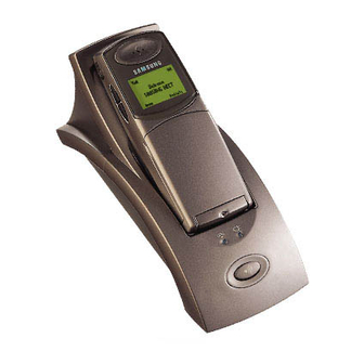
2-1-5 Charging the Handset Before initial operation, you should fully charge the handset for more than 10 hours. To charge the handset, simply place it in the base unit. The handset can be charged facing up. When the handset battery is charging, the handset automatically turns on and the battery icon in the right corner of the display scrolls. -
Page 12: Lcd Window Icon Descriptions
1. To turn on the handset when the display is off, press key. The display shows the handset and base number, and the greeting message SAMSUNG as shown below. (To change the greeting, see page 42) The phone is now ready for use. -
Page 13: Choosing Dial Mode
2-1-8 Choosing Dial Mode In order to provide compatibility with most telephone systems, your phone can be set to either pulse-dialling (same as rotary), or tone dialling (DTMF). Your phone is preset to tone mode. 1. In the Standby mode, press the Menu soft key to access the menu mode. 2. -
Page 14: General Functions
2-2 General Functions 2-2-1 Making a Call 1. Open the flip cover, and press key. You hear a dial tone. Note: If you turn the Active Flip feature on, you do not need to press the key. For details, see page 50. 2. -
Page 15: Camp On Busy
2-2-2 Camp On Busy (Available only when you have more than one handset) This feature allows your handset to wait for connection to the telephone line currently engaged by another handset. Your handset rings when the telephone line becomes free. 1. -
Page 16: Receiving A Call
2-2-3 Receiving a Call When somebody calls you, the phone rings. Also, the (( )) icon in the middle of your handsetÕs display and the telephone lamp on the left of the base will start to blink. The callerÕs phone number will be displayed if the telephone network has transmitted the necessary information. -
Page 17: Caller Id Display
2-2-4 Caller ID Display Caller ID displays the callerÕs name and number, as well as the date and time that the call was received. This feature is available on your phone if the callerÕs network transmits the necessary information. You can use this feature only when the callerÕs service network transmits the callerÕs information. -
Page 18: Last Number Redial
2-2-5 Last Number Redial Your phone allows you to call the most recently dialled numbers again. The phone stores the last 10 numbers you called. To Dial the Last Number 1. Press the Redials soft key in the Standby mode. The last number you dialled is displayed. 2. -
Page 19: Battery Level Indicator
2-2-6 Battery Level Indicator icon is continuously displayed in the upper line of the LCD window. The icon shows the level of your battery. The more bars you see, the more power you have left. H S ( 1 ) B S ( 1 ) S A M S U N G Flat... - Page 20 2-2-8 Adjusting Ring Volume During calls, pressing the keys on the side of the phone affects the ear piece volume. You can adjust the volume from level 1 to 5, and it is preset to level 3. The voice volume is displayed as bars in the LCD window.
-
Page 21: Registered Recall
2-2-11 Registered Recall You can place a new call directly after a call or transfer a call to another extension under PABX, using this feature. To send a flash, simply press the Flash soft key while the line is engaged. The display shows F. 2-2-12 Tone Dial Switchover To access certain services such as voice mail or interactive telephone system features, it is necessary to use tone dialling. -
Page 22: Using The Menus
2-3 Using the Menus A two-level menu structure is available to set the various options available on your phone. You can set the menu options in two different ways, via the soft keys or by using the index system. 2-3-1 Using the Soft Keys The two soft keys are used in the following ways. -
Page 23: Using The Index System
2-3-2 Using the Index System Each menu option is assigned a hierarchical number. You will find the number in the lower right corner of the display, next to (refer to the display diagram above). You can use this number to access the corresponding option directly. - Page 24 2-4 PhoneBook The Phonebook allows you to store frequently used phone numbers and their associated names in your personal directory so that you can easily make a call without having to remember or enter the phone number. You can store up to 70 numbers. 2-4-1 Storing a Phone Number with a Name 1.
-
Page 25: Entering A Name
2-4-2 Entering a Name 1. Press the key labeled with the required letter: ¥ Once for the first letter ¥ Twice for the selected letter ¥ And so on The following characters are available: Characters in the Order Displayed Upper Case Lower Case Space . - Page 26 2-4-3 Dialling a Number in Phonebook Once you have stored phone numbers in the phonebook memory, you can dial them easily whenever you want. One-Touch Dialling Memory addresses 01 through 09 are special one-touch addresses. You can dial the phone numbers stored in the Phonebook memory from 01 through 09 simply by pressing one key.
- Page 27 2-4-4 Searching for Numbers in Memory If you do not remember which telephone numbers have been stored in the various memory addresses, you can scan through the memory until you find the one you are looking for. By Name 1. Press the Menu soft key. Phonebook appears. 2.
-
Page 28: Phonebook Options
2-4-5 Erasing All Numbers 1. Press the Menu soft key. Phonebook appears. 2. Press the Select soft key to access Phonebook menu. The phonebook options are displayed. 3. Press the soft key until All Erase is selected, then press the Select soft key. You are asked if you are sure you want to erase all numbers stored in your phonebook memory. - Page 29 2-5 Received Calls (Caller ID) When you receive a call, the callerÕs phone number is shown on your phoneÕs display, if it is available from the network on which the call was made. The last 20 numbers received are stored in your phone and you can view the list and dial the numbers.
-
Page 30: Received Calls Options
2-5-2 Received Calls Options When you are viewing received numbers, Options appears above the left soft key to allow you to access the received call options, described in the following paragraphs. Accessing the Options 1. Press the Options soft key when it appears. The options are displayed. 2. - Page 31 5. Press the OK soft key to save the setting. Note: If you want to restore the greeting message to the default setting, SAMSUNG, erase all the existing messages and press the OK soft key.
- Page 32 2-7 Ring You can use the Ring menu to customize various sound settings such as ring volume, type and tone. Also you can delay the ring for a specified time via the menu. 2-7-1 Choosing Ring Tone You can define your own ring sound. Ten ring tones are available.The factory default setting is ÔTone 1Õ. 1.
- Page 33 2-7-3 Choosing Alert Type This option allows you to indicate how you wish to be informed of any incoming calls. The following options are available. 1. In the Standby mode, press the Menu soft key. 2. Press the soft key repeatedly until Ring appears, then press the Select soft key. 3.
- Page 34 2-7-4 Unique Ring Tones for selected calls This new feature allows you to distinguish between different callers by assigning unique ring tones to specific numbers stored in your handset When a call is received from a specified number, you will hear a unique ring sound that can only be heard when that specific number calls.
-
Page 35: Operations & Installation
2-7-5 Ring Delay Time If you activate the ring delay time, your handset will not ring for a specified delay time while other handsets are ringing. If you wish, you can answer the call within the delay time on your handset. 1. -
Page 36: Base Number Display
2-8 Settings Many different features of your phone can be customized to suit your preferences. All of these features are accessed via the Settings menu. 2-8-1 Tone/Pulse Refer to page 2-2-12. 2-8-2 Call Time Display If you turn this feature on, the handset automatically times the duration of calls. The handset displays the call duration both during your call and for a few seconds after your call is completed. -
Page 37: Language Selection
2-8-4 Active Flip This feature allows you to automatically engage the telephone line by opening the flip cover. When this feature is set to ON, there is no need to press the key. This feature is preset to OFF at factory. 1. -
Page 38: Call Barring
2-9-1 Call Barring It is possible to set the phone to restrict numbers that can be dialled. The phone cannot dial a phone number beginning with the numbers that you specify. You can set up to 4 different restricted numbers containing up to 4 digits each. If you turn the feature on, the handset requires a PIN code when the restricted number is dialled. -
Page 39: Registering A New Handset
2-9-2 Registering a New Handset The handset supplied with the base unit is already registered as handset 1. Each additional handset you purchase must be registered to the base unit. 1. Press and hold the Paging key on the base for more than 3 seconds. The light is blinking. 2. -
Page 40: Intercom Between Handsets
2-9-3 Intercom Between Handsets (Available only when you have more than one handset) If you have multiple handsets registered with the base, two handsets can talk to each other on an internal intercom call, while a third handset can be on an external call. 1. -
Page 41: Call Transfer Between Handsets
2-9-4 Call Transfer Between Handsets (Available only when you have more than one handset) You can transfer a call from one handset to another. 1. During a telephone conversation, press key. Your caller will be put on hold and will hear music. INTERCOM ->... - Page 42 2-9-6 Changing PIN (Personal Identification Number) The PIN is required when you access System menus. The PIN is preset to Ô0000Õ at factory. You can change the PIN code. 1. In the Standby mode, press the Menu soft key. 2. Press the soft key repeatedly until System appears, then press the Select soft key.
-
Page 43: Reset Handset
¥ Active Flip: OFF ¥ PIN code: 0000 ¥ Auto Find: OFF ¥ No number barred ¥ Greeting Message: SAMSUNG ¥ Key Volume : Level 1 ¥ Voice Volume : Level 3 ¥ Unique Ring Tone: OFF Note: The Dial type will not change even after resetting the handset. -
Page 44: Selecting Base Manually
2-10 Base The SP-R6100 handset may be used with up to four base units. To use the handset with more than one base unit, you must register the handset to each base unit. Refer to ÔRegistering a New HandsetÕ ON 2-9-2. -
Page 45: Finding Base Automatically
2-10-2 Finding Base Automatically With the ÔAuto FindÕ feature set to ON, if you are moving around, and lose contact with the base unit, the handset will automatically find the first available base unit. The feature is preset to OFF. 1. -
Page 46: Troubleshooting
2-10-3 Troubleshooting Symptom Check ¥ Check that the power adapter is properly connected. ¥ Check that the telephone line cord is properly connected. No operation ¥ Check that the handset is fully charged. ¥ Check that the handset batteries are installed properly. ¥... -
Page 47: Exploded View & Parts List
3. Exploded View & Parts List 3-1 SP-R6100 HANDSET P/L Location No Code No Description Specification QÕty GG74-00022A WINDOW-TAPE GG72-00049A WINDOW-LCD GG74-00018A TAPE-WINDOW GG72-00042A FLIP-COVER MAGNETIC 15X2Xt0.8 GG68-30545A LABEL(R)-FLIP GG73-00012A KEY-VOLUME GG72-00057A FRONT-COVER GH75-00046A MEC. HINGE GG73-00014A KEY-PAD GG73-00013A HOLDER-MIC SUA. - Page 48 3-2 SP-R6100 HANDSET Exploded View Exploded View & Parts List...
- Page 49 3-3 SP-R6100 BASE P/L Location No Code No Description Specification QÕty GG72-00047A BASE-UPPER GG72-00051A BACK-COVER 6003-001051 SCREW-TAPTITE TAPTITE, BH, +, 2, M2.6X8 GG72-00050A LED-LENS GG72-00048A KEY-TOP GG73-00016A KEY-RUBBER GG72-00053A SHIELD-COVER(B) GG75-00026A MEC. TERMINAL 6002-000352 SCREW-TAPTITE TAPTITE, PWH, +, M2.5X4 SUA. LOGIC BOARD...
- Page 50 3-4 SP-R6100 BASE Exploded View Exploded View & Parts List...
- Page 51 3-5 SP-R6100 CHARGER P/L Location No Code No Description Specification QÕty GG72-00054A CHARGER-UPPER GG75-00028A MEC. TERMINAL(B) 6002-000352 SCREW-TAPTITE TAPTITE, PWH, +, 2, M2.5X4 SUA. CHG BOARD GG72-00055A CHARGER-LOWER 6002-000397 SCREW-TAPTITE TAPTITE, B, BH, +, M2X6 GG73-00005A FOOT-RUBBER(A) GG61-40101A FOOT-RUBBER GG68-00201A LABEL ID-CHARGER Exploded View &...
- Page 52 3-6 SP-R6100 CHARGER Exploded View Exploded View & Parts List...
- Page 53 3-7 SP-R6100 PACKING P/L Location No Code No Description Specification QÕty USERS MANUAL GG97-01753A MEA BASE HOUSING GG69-10874A BOX-ADAPTOR BATTERY GG97-01752A MEA. H/S HOUSING EAR MIC. TEL LINE GG69-00026A CUSHION-CASE GG69-00025A BOX-UNIT Exploded View & Parts List...
- Page 54 3-8 SP-R6100 PACKING Exploded View Exploded View & Parts List...
-
Page 55: Electrical Parts List
4. Electrical Parts List 4-1 SP-R6100 Hand Logic Parts List SEC CODE VENDOR CODE VENDOR Q’T REFERENCE DESCRIPTION 0402-001075 MBR0520LT1 MOTOROLA DIODE 0404-000116 BAS4004 SIEMENS DIODE-SCHOTTKY 0405-001024 1SV276 TOSHIBA 505, 506 VARACTOR DIODE 0405-001054 BB833 SIEMENS DIODE 0406-001012 SM12 SEMTECH... - Page 56 SEC CODE VENDOR CODE VENDOR Q’T REFERENCE DESCRIPTION 2007-000618 RC1608J240CS 24, 1608 2007-000775 RC1005J333CS 33K, 1005 2007-000839 RC1608J390CS 101, 102 39, 1608 2007-000982 RC1005J542CS 5.6K, 1005 2007-001316 RC1005J821CS 534, 540, 603 820, 1005 2007-001320 RC1005J182CS 122, 123, 543, 544 1.8K, 1005 2007-001323 RC1005J302CS 3K, 1005...
- Page 57 SEC CODE VENDOR CODE VENDOR Q’T REFERENCE DESCRIPTION 2203-000799 GRM40X7R333K25PT MURATA 33NF, 1608 2203-000870 GRM36COG030C50PT MURATA 3PF, 1005 2203-000940 GRM36COG471J50PT MURATA 180, 536 470PF, 1005 2203-001017 C1608TH1H040CT000 521, 548, 559, 563, 599 4PF, 1005 2203-001072 GRM36COG560J50PT MURATA 56PF, 1005 2203-001140 GRM40X7R683K25PT MURATA 120, 122, 125, 126, 127...
- Page 58 18NH, 1005 2703-001790 LL1005-FH3N3S TOKO 506, 507 3.3NH, 1005 2703-001785 BDS-5445-101K BUJEON 100uH 2703-001793 BDS-4532-100M BUJEON 100uH 2801-003780 SQ6U10368F2EED SAMSUNG ELE X-TAL 2802-001016 B69610-H1397-B306 SIEMENS TX RESONATOR 2903-001196 B69812-N1897-L820 SIEMENS BPF FILTER 2904-001158 B3911-B8104-L100 SIEMENS SAW FILTER 3002-001091 PKM35-4A40 MURATA...
- Page 59 4-2 SP-R6100 Base Logic Parts List SEC CODE VENDOR CODE VENDOR Q’T REFERENCE DESCRIPTION 0402-000318 SIZB60 PSHINDENGEN BRIDGE DIODE 0403-001047 BZX84C12 PHILIPS 1, 2 ZEMER DIODE 0403-001085 1SMB5927BT3 MOTOROLA ZEMER DIODE 0404-000116 BAS40-04 SIEMENS DIODE 0405-001024 1SV276 TOSHIBA 505, 506...
- Page 60 SEC CODE VENDOR CODE VENDOR Q’T REFERENCE DESCRIPTION 2007-000155 RC1005J273CS 82, 531 27K, 1005 2007-000159 RC1005J563CS 33, 100 56K, 1005 2007-000162 RC1005J104CS 44, 45, 47 100K, 1005 2007-000163 RC1005J124CS 120K, 1005 2007-000171 RC1005J000CS 16, 52, 68, 71, 97, 98 0, 1005 2007-000172 RC1005J100CS 10, 1005...
- Page 61 SEC CODE VENDOR CODE VENDOR Q’T REFERENCE DESCRIPTION 2203-000455 GRM40COG102J50PT MURATA 35, 36 1NF, 2012 2203-000489 GR36X7R222K50PT MURATA 2.2NF, 1005 2203-000550 GR36COG200J50PT MURATA 20PF, 1005 2203-000628 GR36COG220J50PT MURATA 22PF, 1005 2203-000643 GRM36COG240J50PT MURATA 24PF, 1005 2203-000654 GRM36X7R271K80PT MURATA 31, 32 270PF, 1005 2203-000696 GRM36COG20C50PT...
- Page 62 LL2012-FH82NJ TOKO 82NH, 2012 2703-001722 LL1005-FH18NJ TOKO 500, 510 18NH, 1005 2703-001790 LL1005-FH3N3S TOKO 506, 507 3.3NH, 1005 2801-003780 SQ6U10368F2EED SAMSUNG ELE X-TAL(SMD) 2802-001016 B69610-H1397-B306 SIEMENS TX RESONATOR 2903-001196 B69812-N1897-L820 SIEMENS BPF FILTER 2904-001158 B3911-B8104-L100 SIEMENS SAW FILTER 3722-001239 100860-1...
- Page 63 4-3 SP-R6100 KEY Part List SEC CODE VENDOR CODE VENDOR Q’T REFERENCE DESCRIPTION 1009-001006 A3210ELH ALLEG IC-HALL EFFECT S/W 2007-000102 RC1608J104CS 100K, 1608 2203-000189 GRM39V5V104Z25PT MURATA 100NF, 1608 2203-000440 CL10B102KBNC 1NF, 1608 3003-001044 CMS-2745C BOSUNG 3711-004395 AXN820535 NAIS KEY-HEADER GG59-00001A...
-
Page 64: Block Diagrams
5. Block Diagram 5-1 SP-R6100 Base Logic Block Diagram Block Diagrams... - Page 65 5-2 SP-R6100 RF Block Diagram Stand by & control logic Block Diagrams...
- Page 66 RF PART PMB5722 PMB5420 SPEECH BURST RECEIVER DECODING DECODING SPEECH BURST BUILDING ENCODING PMB4220 TRANSMITTER & PLL ADPCM CODEC INTERFACE FILTER 8K Byte EEPROM CONTROLLER AT24C16 8 BIT IICBUS EEPROM INTERNAL DISPLAY PORT 1 ROM & RAM RSSI PORT X BATT KEYPAD PORT Y...
-
Page 67: Pcb Diagrams
6. PCB Diagrams 6-1 SP-R6100 Base PCB... - Page 68 PCD Diagrams...
- Page 69 6-2 SP-R6100 Base PCB (II)
- Page 70 PCD Diagrams...
- Page 71 6-3 SP-R6100 Handy PCB (I)
- Page 72 PCD Diagrams...
- Page 73 6-4 SP-R6100 Handy PCB (II)
- Page 74 PCD Diagrams...
- Page 75 6-5 SP-R6100 Key PCB (I) PCD Diagrams...
- Page 76 6-6 SP-R6100 Key PCB (II) PCB Diagrams...
- Page 77 6-7 SP-R6100 Charger PCB (I) PCD Diagrams...
- Page 78 6-8 SP-R6100 Charger PCB (II) PCB Diagrams...
-
Page 79: Schematic Diagrams
7. Schematic Diagrams 7-1 SP-R6100 Hand LOGIC Schematic Diagrams... - Page 80 7-2 SP-R6100 Hand RF Schematic Diagrams...
- Page 81 7-3 SP-R6100 BASE LOGIC Schematic Diagrams...
- Page 82 7-4 SP-R6100 Base CLIP Schematic Diagrams...
- Page 83 7-5 SP-R6100 BASE RF Schematic Diagrams...
- Page 84 7-6 HAND KEY Schematic Diagrams...
- Page 85 7-7 CHRGER Schematic Diagrams...
-
Page 86: Usage Of Jig Program
=> When you choose handset in SET SELECTION. - - - SELECT VERSION - - - 0 : SP-R5200 HAND 1 : SP-R6100 HAND Press the number (0/1) and then Press the Enter key. => 3. THIRD SCREEN --- NATION SELECTION --- 0) U.K.(Emergency) - Page 87 4. MAIN SCREEN (In case of HAND set) SR-R6100(DECT) HANDSET (UK) EEPROM WRITING X-TAL ADJUSTING RESULT F1:ID READ F3:ID WRITE F5:NAT OPT F7:CLK ADJ F9:RF TEST ALT+X:EXIT 1. F1 : ID READ (Automatically read the test setÕs ID.) 2. F3 : ID WRITE (You can write some ID which you want to write.) 3.
- Page 88 ELECTRONICS Samsung Electronics Co.,Ltd.
Need help?
Do you have a question about the SP-R6100 and is the answer not in the manual?
Questions and answers