Advertisement
SERVICE
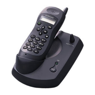
Cordless Telephone
Cordless Telephone
SP-R5100
S E C R E T
Manual
1. Safety Precautions
2. Specification
3. Function Structures
4. Test Mode
5. Component Pin Array
6. Alignment & Adjustment
7. Trouble Shooting
8. PCB Views
9. Electrical Parts List
10. Exploded Views and Parts List
11. Block Diagram
CONTENTS
Advertisement
Table of Contents

Summary of Contents for Samsung SP-R5100
- Page 1 Cordless Telephone SP-R5100 S E C R E T Manual SERVICE Cordless Telephone CONTENTS 1. Safety Precautions 2. Specification 3. Function Structures 4. Test Mode 5. Component Pin Array 6. Alignment & Adjustment 7. Trouble Shooting 8. PCB Views 9. Electrical Parts List 10.
- Page 2 : This is RF module clock input pin(pin number : 2 4) and its frequency is 1 3.8 2 4M H z . Q) SYS CLOCK : This is RSSI output pin(pin number : 1 9) and its voltage level is related to signal level. R) RSSI Samsung Electronics...
- Page 3 Normal or trickle mode is selected by the MPU pin xx. In case of normal charge mode, the MPU goes to ° ∞ H I G H °± state and turns on Q1 8. The Q2 0 is controlled by Q1 8. Samsung Electronics...
- Page 4 : This is RF module clock input pin(pin number : 2 4) and its frequency is 1 3.8 2 4M H z . Q) SYS CLOCK : This is RSSI output pin(pin number : 1 9) and its voltage level is related to signal level. R) RSSI Samsung Electronics...
- Page 5 The TX digital signal from the RMT RF inputs the BASE RF module and then the digital siginal is converted into analog audio by the MPU. Those audio signals go to the TEL LINE through the SPEECH IC e ) INDICATION CIRCUIT This circuit consists of LEDS to display the baseset operation. Samsung Electronics...
- Page 6 5. BASE LOGIC...
- Page 7 6. REMOTE LOGIC...


Need help?
Do you have a question about the SP-R5100 and is the answer not in the manual?
Questions and answers