Table of Contents
Advertisement
Quick Links
Advertisement
Table of Contents

Subscribe to Our Youtube Channel
Related Manuals for Axminster UV-180DS


Summary of Contents for Axminster UV-180DS
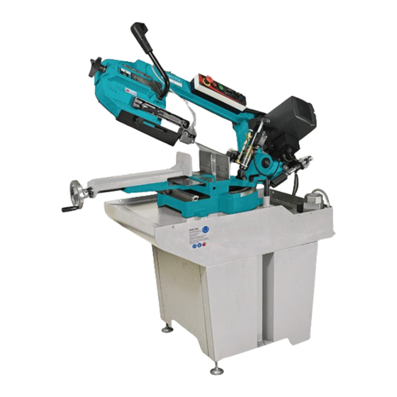
- Page 1 Code 103629 UV-180DS 7" Bandsaw AT&M: 27/01/2017...
-
Page 2: Table Of Contents
TABLE OF CONTENTS Warning................................1 Prior to Operation ...............................2 Before Cutting ..............................2 Assembly Material Stopper ..........................2 The Base ................................2 Coolant System ..............................2 Operation of Control Box ............................3 Hydraulic Feed Selector Operation ........................3 Spring Setting ..............................3 Adjusting movable Blade Guide .........................3 Vise Operation ..............................4 Adjusting Blade Tension .............................4 Changing Blades ..............................4 Adjusting Blade Square to Table ........................5... -
Page 3: Warning
Warning Read and understand the entire instruction manual before operating machine. Always wear approved safety glasses/face shields while using this machine. Make certain the machine is properly grounded. Before operating the machine, remove tie, rings, watches, other jewelry, and roll up sleeves above the elbows. -
Page 4: Prior To Operation
Prior to Operation Check to see blade tooth direction matches diagram on saw body. Check to see that blade is properly seated on wheels after proper tension has been applied. Set blade guide roller bearing snug against blade. See Adjusting Blade Guide Bearings for more details. -
Page 5: Operation Of Control Box
Hydraulic Feed Selector Operation The hydraulic feed selector is used to control cutting feed down rate and lock the bow in the proper position. To turn off the flow of hydraulic fluid, pull lever (B) to vertical with the cylinder. To turn the hydraulic fluid on, pull lever (B) to parallel with the cylinder. -
Page 6: Vise Operation
To set the blade tension without the use of a CAUTION! blade tension gauge: NEVER OPERATE SAW WITHOUT BLADE GUARDS IN PLACE. Disconnect machine power, open wheel covers to install blade belt between wheels and insert blade between bearings on blade guides. Tension blade slightly to remove any sag in blade between blade wheels. -
Page 7: Adjusting Blade Square To Table
Carefully remove old blade. Caution: blade Connect machine to the power source. teeth are sharp. Handle with care. Install new blade (E) by placing blade between Note: If adjustment to square blade to table is blade guides (F) first. Make sure blade teeth necessary, be sure to check blade adjustments face the same direction as indicated on the again. -
Page 8: Adjusting Blade Guide Bearings
Move saw bow to proper height position and Turn nut (B) to adjust eccentric bearing shaft to lock in place by shutting off the hydraulic the blade (the other side bearing shaft is fixed). cylinder valve. Blade should still move up and down freely Confirm that blade tension is set properly. -
Page 9: Maintenance
Maintenance 4. The chart is not expected to be correct for all cases. It is intended as a general guide to good sawing practices. Your blade supplier or qualified engineers should be you most reliable WARNING source for correct information on operational Disconnect machine from the power source details of saw blades and their use. -
Page 10: Circuit Diagram
Circuit Diagram... - Page 11 SECTION A - PARTS LIST Part No. Stock No. Description Size Q'ty UV180A105 Base Socket Head Cap Screw M10x30 Angle Plate M5x10 Cross Round Head Screw UV180A309 Swivel Plate Scale UV180A106 Vise Base M8x65 Socket Head Cap Screw UV180A201 Swiveling Shaft UV180A314 Vise Plate M6x16...
- Page 12 SECTION A - PARTS LIST Part No. Stock No. Description Size Q'ty UV180A315 Pointer M5x10 Cross Round Head Screw UV180308A Spring Lower Bracket UV180405A Spring Spring Washer M5x16 Socket Head Cap Screw UV180308 Spring Upper Bracket 12x21x2 Flat Washer Spring Washer M12x30 Hex Cap Screw Wing Hex Nut...
- Page 14 SECTION B - PARTS LIST Part No. Stock No. Description Size Q'ty UV180101 L25A5-35 Cable Tie M5x10 Cross Round Head Screw Motor Relay M5x35 Socket Head Cap Screw UV180401 Plastic Cover UV180219 Axle UV180408 Hydraulic Cylinder Hex Nut UV180A101 Upper Bracket 8x18x2 Flat Washer M8x20...
- Page 15 SECTION B - PARTS LIST Part No. Stock No. Description Size Q'ty 540mm Hose UV180106 Rear Saw Wheel 13mm Hose Clamp 9160408-1 M9TM7 Valve M5x10 Cross Round Head Screw 9160321 Brace 1660mm Hose UV180315 Cover UV180509 6007 Ball Bearing UV180217 Bushing UV180506 6204...
- Page 17 SECTION C - PARTS LIST Part No. Stock No. Description Size Q'ty UV180A302 Right Stand M8x16 Hex Cap Screw Flat Washer UV180A304 Rear Stand UV180A305 Front Stand M8x16 Hex Cap Screw 331D4-37 1/2" Level Pad 1/2" Hex Nut UV180A303 Left Stand Flat Washer Hex Nut UV180A301...
- Page 20 Normal wear and tear; misuse, abuse and neglect are excluded and the machine should not have been engineering machines, Axminster Air compressors and Air Tools, and bench top grinders - no modified in any way. Please do not attempt to service the product without first contacting us; we are registration necessary just proof of purchase.
Need help?
Do you have a question about the UV-180DS and is the answer not in the manual?
Questions and answers