Table of Contents
Advertisement
Advertisement
Table of Contents
Troubleshooting

Related Manuals for Matrix T50x-02


Summary of Contents for Matrix T50x-02
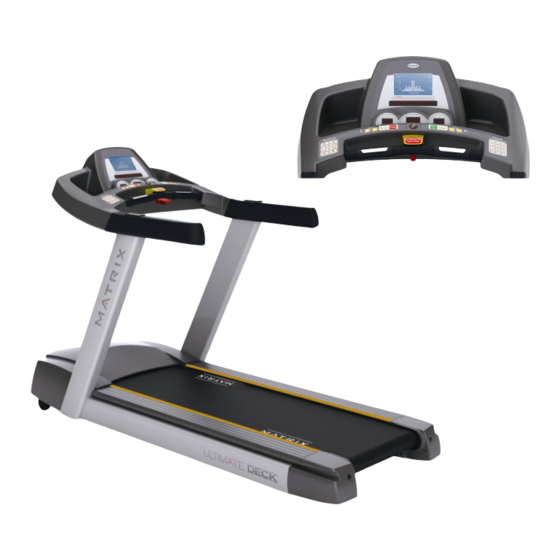
- Page 1 Matrix T50x-02 / T50x-U-02 SERVICE MANUAL...
-
Page 2: Table Of Contents
TABLE OF CONTENTS SECTION 1: : : : SERIAL NUMBER LOCATION- - - - - - - - - - - - - - - - - - - - - 5 ~ 6 SECTION 2: : : : MOVING THE UNIT- - - - - - - - - - - - - - - - - - - - - - - - - - - - - 7 ~ 8 SECTION 3:... - Page 3 TABLE OF CONTENTS SECTION 7: : : : TROUBLESHOOTING- - - - - - - - - - - - - - - - - - - - - - - - - - - - - 29 7.1 Electrical block diagram - - - - - - - - - - - - - - - - - - - - - - - - - - - - - - - - - - - - - 30 7.2 Wire pin definition - - - - - - - - - - - - - - - - - - - - - - - - - - - - - - - - - - - - - - - - -31 7.3 MCB LED instruction- - - - - - - - - - - - - - - - - - - - - - - - - - - - - - - - - - -- - -32~33 7.4 MCB wiring connection- - - - - - - - - - - - - - - - - - - - - - - - - - - - - - - - - - - - - 34...
- Page 4 TABLE OF CONTENTS SECTION 8: : : : PART REPLACEMENT GUIDE- - - - - - - - - - - - - - - - - - - - - 50 8.1 Removal of plastic shroud - - - - - - - - - - - - - - - - - - - - - - - - - - - - - - - - - - 51 8.2 Rear roller removal - - - - - - - - - - - - - - - - - - - - - - - - - - - - - - - - - - - - - - -52 8.3 Side rail removal - - - - - - - - - - - - - - - - - - - - - - - - - - - - - - - - - - - - - - - - 53 8.4 Deck Removal/Replacement - - - - - - - - - - - - - - - - - - - - - - - - - - - - - - - - 54...
-
Page 5: Section 1: : : : Serial Number Location
SECTION 1 SERIAL NUMBER LOCATION... -
Page 6: Section 1: : : : Serial Number Location
Matrix T50x Serial Number Location... -
Page 7: Section 2: : : : Moving The Unit
SECTION 2 MOVING THE UNIT... -
Page 8: Unpacking The Treadmill
UNPACKING THE TREADMILL SETTING UP THE TREADMILL The MATRIX treadmill is inspected before it is packaged. It is shipped in two separate pack- ages: the frame and the console. Carefully unpack the unit and dispose of the box material. CAUTION... -
Page 9: Section 3: : : : Important Safety Instructions
SECTION 3 IMPORTANT SAFETY INSTRUCTIONS... -
Page 10: Read And Save These Instructions
1.1 Before getting Started It is the sole responsibility of the purchaser of Matrix Fitness Systems products to instruct all individuals, whether they are the end user or supervising personnel, on proper usage of the equipment. It is recommended that all users of Matrix Fitness Systems exercise equipment be informed of the following information prior to its use. - Page 11 When using an electrical product, basic precautions should always be followed including the following: DANGER: To reduce the risk of electric shock: Always unplug this equipment from the electrical outlet immediately after using and before cleaning. WARNING : To reduce the risk of burns, fire, electrical shock or injury to persons that may be associated with using this product: •...
-
Page 12: Electrical Requirements
120v units The Matrix T50X, T50X-U 120 treadmill is for use on a nominal 120-volt circuit and has a non- looped grounding plug. Make sure that the 120-volt treadmill is connected to an outlet, NEMA 5-20R, having the same configuration as the plug. -
Page 13: Section 4: : : : Preventative Maintenance
SECTION 4 PREVENTATIVE MAINTENANCE... -
Page 14: Maintenance Checklist
4.1 MAINTENANCE CHECKLIST FOR BEST PERFORMANCE WE RECOMMEND THE FOLLOWING MAINTENANCE SCHEDULE: Item Weekly Monthly BI-annually Annually Console Bolts Inspect Frame Clean Inspect Assure Running Belt Clean Inspect Tighten Power Code Inspect Console Clean Inspect Bottle Holders Clean Handlebars Clean Inspect Handlebars Bolts Inspect... -
Page 15: Recommended Cleaning Tips
4.2 RECOMMENDED CLEANING TIPS Use a soft, clean cotton cloth. DO NOT use paper towels to clean surfaces on the treadmill. Paper towels are abrasive and can damage surfaces. 2. Use a mild soap and damp cloth. DO NOT use ammonia based cleaner. This will cause discoloring of the aluminum and plastics it comes into contact with. -
Page 16: Deck And Belt Replacement
2 inches / 5 centimeters on both sides removing any dust or debris. The deck can be flipped and reinstalled or replaced by an authorized service technician. Please contact Matrix Fitness Systems or authorized dealers for more information. -
Page 17: Check For Damaged Parts
Ensure that any person(s) making adjustments or performing maintenance or repair of any kind is qualified to do so. Matrix Fitness Systems will provide service and maintenance training at our corporate facility upon request or in the field if proper arrangements are made. -
Page 18: Adjusting The Belt
4.5 ADJUSTING THE BELT After placing the treadmill in the position it will be used, the belt must be checked for proper tension and centering. The belt might need to be adjusted after the first two hours of use. Temperature, humidity, and use cause the belt to stretch at different rates. -
Page 19: Clean The Grooves Procedures
4.6 CLEAN THE GROOVES PROCEDURE Frequency: Every 3 months Caution: If dirty grooves in the drive belt, motor and roller pulley, there will be noises while running. Procedure: 1.Remove the drive belt and check the grooves in belt for dirt or dust and clean it. 2.Check the grooves in motor pulley for dirt or dust and clean it... -
Page 20: Deck Re-Waxing Procedure
4.7 DECK RE-WAXING PROCEDURE Purpose : To ensure the maximum life of your treadmill, follow these steps at Purpose : regular intervals. The timing of running belt and deck maintenance : The timing of running belt and deck maintenance Each 6 months to lubricate by wax powder. One year to flip the running deck. - Page 21 WAXING PROCEDURE: WAXING PROCEDURE: Warm deck and belt by walking on treadmill for 3 or more minutes at a minimum speed of 3 mph (4.8 kph). Turn off and unplug the treadmill. Sprinkle approximately 1/2 scales of wax under the running belt. (It is useful to lightly blow the wax to the center of the belt.) Turn the unit on and walk the wax in for 3-4 minutes at 1 mph.
-
Page 22: Section 5 : Overlay And Workout Description
SECTION 5 OVERLAY AND WORKOUT DESCRIPTION... -
Page 23: T50X Console Description
5.1 T50x Console description WORKOUT keys : Simple program view and selection buttons. Quick START: One touch Start and Quick Start. ENTER: To confirm each program setting. up/down INCLINE: Easy information and incline selection. up/down speed : Easy information and speed selection. emergency stop / Immobilization : To stop all functions and immobilize the unit. -
Page 24: T50X-U Console Description
5.2 T50x-U Console description WORKOUT keys : Simple program view and selection buttons. Quick START: One touch Start and Quick Start. ENTER: To confirm each program setting. up/down INCLINE: Easy information and incline selection. up/down speed : Easy information and speed selection. emergency stop / Immobilization : To stop all functions and immobilize the unit. -
Page 25: Section 6: : : : Engineering Mode
SECTION 6 ENGINEERING MODE... -
Page 26: Engineering Mode
Engineering MODE The Engineering Mode allow the club owner to customize the treadmill for the club. To enter the Engineering Mode, press and hold down the "INCLINE " and "SPEED " keys. ▼ ▼ Continue to hold down these two keys until the INSTRUCTION CENTER displays “MANAGER MENU”. - Page 27 CUSTOM DEFAULT RANGE UNIT DESCRIPTION SETTING This option enables fitness club managers to set the program maximum workout MAXIMUM duration limits during peak and non-peak 10~99 Minute TIME hours of club traffic. Active variable displayed in the TIME display after change. DEFAULT TIME 10~Max Minute...
- Page 28 CUSTOM DEFAULT RANGE UNIT DESCRIPTION SETTING PAUSE This is the maximum time during which 60 sec 30~180 sec TIME a workout can remain in pause mode. The language of the INSTRUCTION CENTER LANGUAGE English Display. When the machine set to T50x-IFI will not have T50x / MODEL T50x...
-
Page 29: Section 7: : : : Troubleshooting
SECTION 7 TROUBLE SHOOTINGS... -
Page 30: Electrical Block Diagram
7.1 Electrical block diagram... -
Page 31: Wire Pin Definition
7.2 Wire pin definition W35 -- Digital Comm Wire W38 -- Grip Pulse Wire... -
Page 32: Mcb Led Instruction
7.3 MCB LED instruction... - Page 33 Reference Description Designator Indicates if the upper console is commanding elevation DOWN. LED display: DOWN LED2 Light : Normally Off : No command from console into elevation motor Indicates if the upper console is commanding elevation UP. LED display: LED3 Light : Normally Off : No command from console into elevation motor Indicates if console voltage supply is present.
-
Page 34: Mcb Wiring Connection
7.4 MCB wiring connection CN9 -------AC motor cable socket CN1-------Input power cable socket CN13--------External fan cable socket CN7--------Digital communication cable socket CN6--------Elevation motor cable socket CN8--------Adaptor power cable socket (only for T1xe / T3xe) -
Page 35: T50X Switch Setting Definition
7.5 T50x switch setting definition Model Collocation motor Switch definition T1x(TM522) / T3x(TM523) T7000PRO(TM51 2C) / T60(TM518C) -
Page 36: Error Message 0140 / 01A0 / 01A2 Troubleshooting
7.6 Error message 0140 / 01A0 / 01A2 troubleshooting [Symptom ] 0140 - Incline motor operation failed. 01A0 - Incline motor disconnected. 01A2 - Incline motor is detected in the reverse of the position indicated by the potentiometer. [Solution] a. Check the connection of the incline motor cable at the MCB. b. -
Page 37: Error Message 01A3 Troubleshooting
7.7 Error message 01A3 troubleshooting [Symptom ] Motor is disconnected. [Solution] a. Check the connection of the motor cable at the MCB (Figure A). b. Check if the MCB LED DSP1 (MCU) is lit (Figure B). c. If LED DSP1 is blinking, the motor should be replaced. d. -
Page 38: Error Message 0144 / 02B6 / 02B7 / 02B8 / 01A8 / 02B5 Troubleshooting
7.8 Error message 0144 / 02B6 / 02B7 / 02B8 / 01A8 / 02B5 troubleshooting [Symptom ] 0144 - Motor over current. 02B6 - Speed up is overcurrent. 02B7 - Speed down is overcurrent. 02B8 - Running status is overcurrent. 01A8 - Internal electronic thermal relay protection: motor load is too large. -
Page 39: Error Message 0141 Troubleshooting
7.9 Error message 0141 troubleshooting [Symptom ] a. Motor over temperature. [Solution] a. Check the connection of the motor cable at the MCB (Figure A). b. Use a multi-meter to check the motor wire circuit. Set the multi-meter to Ohms and place both terminals on the blue wires of the motor cable (Figure B). -
Page 40: Error Message 02Ad Troubleshooting
7.10 Error message 02AD troubleshooting [Symptom ] a. MCB is over temperature. [Solution] a. Check if both fans are operating (there is a fan mounted to the MCB itself as well as an external fan). Also check the connection of the fans at the MCB (Figure A). b. -
Page 41: Error Message 02B2 Troubleshooting
7.11 Error message 02B2 troubleshooting [Symptom ] The emergency circuit on the interface board active. [Solution] a. Check the connection of the safety key (emergency stop) switch (Figure A). If the switch is always open or shorted out, replace the switch. b. -
Page 42: Error Message 02B9 / 02Ba/ 02Bb / 01Ab Troubleshooting
7.12 Error message 02B9 / 02BA/ 02BB / 01AB troubleshooting [Symptom ] 02B9 - The inner memory IC data write error. 02BA - The inner memory IC data read error. 02BB - Inverter hardware interrupt error. 01AB - Inverter Error [Solution] a. -
Page 43: Error Message 04A0 Troubleshooting
7.13 Error message 04A0 troubleshooting [Symptom ] a. UCB no communication received. [Solution] a. If the display is giving a 04A0 error, LED DSP2 (RS485) should be light (Figure A). If this light is not on and a 04A0 error is present, replace the UCB. b. -
Page 44: Error Message 04B0 Troubleshooting
7.14 Error message 04B0 troubleshooting [Symptom ] a. MCB no communication received. [Solution] a. If the display is giving a 04B0 error, LED DSP2 (RS485) should be light (Figure A). If this light is not on and a 04B0 error is present, replace the UCB. b. -
Page 45: Error Message 01A4 / 01A5 / 01A6 / 02A7 Troubleshooting
7.15 Error message 01A4 / 01A5 / 01A6 / 02A7 troubleshooting [Symptom ] 01A4 - Main motor U phase disconnection 01A5 - Main motor V phase disconnection 01A6 - Main motor W phase disconnection 02A7 - Inverter output side is detected abnormal sudden increase over current [Solution] a. -
Page 46: Error Message 02A2 / 0241 Troubleshooting
7.16 Error message 02A2 / 0241 troubleshooting [Symptom ] 02A2 - DC high voltage converter to detect the internal side of over-voltage phenomenon. 0241 - DC high voltage side of the internal drive is too low to detect. [Solution] a. Please check if the input power is normal and reboot power again.(Figure A) b. -
Page 47: Error Message Immobilized Troubleshooting
7.17 Error message IMMOBILIZED troubleshooting [Symptom 2 of treadmill will not start ] Press start the LED display will show “IMMOBILIZED” [Cause] Machine lock [Solution] Please hold machine function “FIT TRAINER” & “MULTI FX” key for 3’s to unlock... -
Page 48: How To Test Incline Motor Function Troubleshooting
7.18 How to test Incline motor function troubleshooting [Symptom 2 of treadmill will not start ] To verify Incline motor function (Test VR value) [Cause] If the VR value reading show “0” during Auto Check, will cause 01A0. [Solution] Please release incline tube (Figure A), and run “Auto check” After start “Auto Check”. -
Page 49: Incline Motor Jammed And 01A0 Troubleshooting
7.19 Incline motor jammed and 01A0 troubleshooting [Symptom 2 of treadmill will not start ] If the Incline tube jammed with the bottom or error code “01A0” appear. [Cause] Error code 01A0 [Solution] Please release incline tube (Figure A), and turn on the power. After turn on the power, Machine will find BDC (bottom dead center) (Figure B) (Figure B) (Figure A) -
Page 50: Section 8: : : : Part Replacement Guide
SECTION 8 PARTS REPLACEMENT... -
Page 51: Removal Of Plastic Shroud
8.1 Plastic shroud removal 1. Remove the 6 pcs screw using Phillips screwdriver. (Figure A) 2. Remove motor cover. (Figure B) Figure A Figure B... -
Page 52: Rear Roller Removal
8.2 Rear roller removal 1. Turn off power and disconnect the cord from the machine 2. Remove one of the end caps using a Phillips screwdriver (Figure A) 3. Remove both roller adjustment screws using an 8mm Allen wrench ( Figure B and C) 4. -
Page 53: Side Rail Removal
8.3 Side rail removal 1. Remove the end cap as outlined in section 8.2 2. Remove the reinforce tube two screw using a 4mm Allen wrench (Figure A) 3. Slide the rail off the back of the treadmill ( Figure B ) Figure A Figure B... -
Page 54: Deck Removal/Replacement
8.4 Deck removal / Replacement 1. Remove the front shroud as outlined in section 8.1 2. Remove four deck screws using a 5mm Allen wrench (Figure A) 3. Remove deck from the running belt (Figure B ) 4. Be careful not to pinch fingers during removal/installation of deck board 5. -
Page 55: Deck Cushion Replacement
8.5 Deck cushion replacement 1. Remove the deck as outlined in section 8.3 2. Holding the bolt with 5mm Allen wrench, loosen the nut with 13mm socket (Figure A and B) 3. For the rear cushion, hold the cushion and remove the 13mm nut (Figure C) Figure A Figure B... -
Page 56: Front Roller Removal
8.6 Front roller removal 1. Remove shrouds as outlined in section 8.1 2. Using a hook or loop of wire, (Figure A) remove the spring from the belt tensioner. The tensioner will now pivot away from the drive belt 3. Remove the front roller mounting screws using 8mm Allen (Figure B and C) 4. -
Page 57: Running Belt Replacement
8.7 Running belt replacement 1. Remove shrouds as outlined in section 8.1 2. Remove rear roller as outlined in section 8.2 3. Remove front roller as outlined in section 8.5 4. Remove deck as outlined in section 8.4 5. Remove the running belt and replace with new belt (Figure A and B) 6. -
Page 58: Motor Control Board (Mcb) Removal
8.8 Motor control board (MCB) removal 1. Remove shroud as outlined in section 8.1 2. Cut any wire ties that are secured to the MCB panel (Figure A) 3. Disconnect wires from the MCB seven connections total (Figure B) 4. Remove four MCB mounting screws using Phillips head screwdriver (Figure C ) Figure A Figure B... -
Page 59: Motor Removal
8.9 Motor removal 1. Remove the front shroud as outlined in section 8.1 2. Release drive belt tensioner as described in section 8.5 3. Disconnect the motor power cable from the motor control board (Figure A) 4. Using the 4mm Allen wrench the ground wire from the motor set (Figure B) Figure A 5. -
Page 60: Drive Belt Removal
8.10 Drive belt removal 1. Remove plastic shroud from machine as outlined in section 8.1 2. Release belt tensioner from drive belt as outlined in section 8.5 3. Remove the front roller screw on the drive belt side, and loosen the screw on the opposite side (Figure A) 4. -
Page 61: Incline Motor Removal/Replacement
8.11 Incline motor removal / Replacement 1. Lift the treadmill and support it so that the wheels are off the floor, or the unit may be tipped onto it’s side (Figure A) 2. Remove the clip from the pin attaching motor shaft to the rack (Figure B and C) 3. - Page 62 Figure D Figure E Figure G Figure F...
-
Page 63: Pcb Removal/Disassembly
8.12 PCB set removal / replacement 1. Remove the four screws from underneath the console. There are arrows stamped in the plastic at the proper openings (Figure A) 2. Disconnect the wires from the PCB. (Figure B and C) Figure A Figure B Figure C... -
Page 64: Quick Key Removal/Replacement
8.13 Quick key set removal / replacement 1. Remove the quick key set two screws using 2mm Allen (Figure A) 2. Disconnect the wires from the quick key set (Figure B) Figure A Figure B... -
Page 65: Handlebar Removal/Replacement
8.14 Handlebar removal / replacement 1. Remove quick key set from machine as outlined in section 8.12 2. Remove bottom cover from handlebar below using screwdriver (Figure A) 3. Remove handlebar from the frame (Figure B and C) Figure A Figure B Figure C... -
Page 66: Pcb Software Installation Sop
8.15 PCB software installation SOP A. Service Tools & Accessories: MSP-FET430 (Please refer the bulletin NB-0506002) Parts NO: 010688-00 Software... - Page 67 Please refer the above photo to set the parameter. Press the File Name Find out the software version file in the computer and then actuate/open the file.
- Page 68 Computer Install the MSP430 Tools...
- Page 69 Press the Load Image, Installation software to MSP430 Tools.
- Page 70 MSP430 Installing the MSP430 cable to console.
- Page 71 1. Press the MSP430 “START” key, the “MODE” light will to glitter about 10 sec, If installing pass, the OK LET light. 2. Drive the machine to provide power for console and then enter into the engineering mode to confirm if the software had been installed/upgraded...
Need help?
Do you have a question about the T50x-02 and is the answer not in the manual?
Questions and answers