Table of Contents
Advertisement
Quick Links
Advertisement
Table of Contents

Related Manuals for Custom Audio Electronics VKP112


Summary of Contents for Custom Audio Electronics VKP112
- Page 1 VKP112 VKP112 USER MANUAL DOMC-0001e Command Reference:...
- Page 2 All rights reserved. Total or partial reproduction of this manual in whatever form, whether by printed or elec- tronic means, is forbidden. While guaranteeing that the information contained in it has been carefully checked, CUSTOM ENGINEERING SPA and other entities utilized in the realization of this manual bear no responsibility for how the manual is used.
- Page 3 PRINTER COMPONENTS A. Front external view Printing mechanism Cutter Paper mouth Paper out Ejector unit mechanism Printing mechanism motor (Fig.1) VKP112 User Manual...
- Page 4 Paper roll holder pivot USB interface connector Near paper end sensor Near paper end connector LINE FEED key Power supply connector FORM FEED key Unblocking lever for printing head POWER ON Led Unblocking lever for ejector unit. (Fig.2) VKP112 User Manual...
- Page 5 CENTRONICS parallel interface connector Paper roll holder pivot Near paper end connector Near paper end sensor Power supply connector LINE FEED key Unblocking lever for printing head FORM FEED key Unblocking lever for ejector unit. POWER ON Led (Fig.3) VKP112 User Manual...
- Page 6 The printer components described previously (see fi g.1) are grouped as follows (see fi g. 2): Ejector unit Metal chassis Paper roll holder unit Electronic board Printing mechanism (Fig.4 ) VKP112 User Manual...
-
Page 7: Table Of Contents
2.3 CENTRONICS PARALLEL INTERFACE ....................2-4 3. TECHNICAL SPECIFICATION 3.1 TECHNICAL SPECIFICATIONS ......................3-1 3.2 DIMENSIONS ............................3-3 3.2.1 VKP112 printer with paper roll holder support.................3-3 4. CHARACTER SETS 4.1 CHARACTER SETS ..........................4-1 APPENDIX A - ACCESSORIES AND SPARE PARTS A.1 ACCESSORIES ............................. A-1 A.1.1 Power supply .......................... - Page 8 TABLE OF CONTENTS Blank page ii VKP112 User Manual...
-
Page 9: Introduction
The printer is not functioning normally despite the fact that all instructions in the users manual have been followed. The printer has been dropped and its outer casing damaged. Printer performance is poor. The printer is not functioning. VKP112 1 User Manual... -
Page 10: Unpacking The Printer
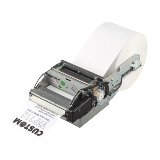
(Fig.1) PRINTER FEATURES The VKP112 printer is designed to emit high-resolution thermal-printed tickets ideal for use in information and multimedia kiosks, self-service machines, no-queue systems, parking areas, gaming machines and toll receipt machines. Two ticket presentation systems are available on the VKP112 printer: - Motor-driven dispenser with sensors on the dispenser that holds the ticket while it is being printed and then delivers it once it has been cut. -
Page 11: Printer Description
• Plastic paper outfeed slot. PRINTER DESCRIPTION The VKP112 printer is comprised of a metal frame, paper roll holder, printing mechanism and cutter. The following keys (see fi g.2) are located on the control panel: LF LINE FEED key (1), FF FORM FEED key (2), POWER ON Led (3), NEAR PAPER END Led (4) and STATUS Led (5). - Page 12 LED signals and the corresponding printer status. STATUS COLOUR DESCRIPTION Printer malfunction Printer ON - no malfunction RECOVERABLE ERROR Fast Overheating BLINKING Slow (for extended period) “No Paper” message Slow (for short period) Printing head turned upwards (Tab.1) 4 VKP112 User Manual...
-
Page 13: Installation And Use
For the power supply, the printer is equipped with a male, 90° mobile screw (pitch 5.08mm) terminal (J5). The signals on the power supply connector pins are as follows: PIN No. SIGNAL 24 Vcc power supply (Tab.1.1) WARNING Respect power supply polarity. VKP112 1-1 User Manual... -
Page 14: Self-Test
Reset buffer........:At Paper End Current ..........:Normal Print Density........:Normal Paper autoload ......:Enabled Reset buffer........:At Paper End Print Density........:Normal [FF] key to enter setup [LF] key to skip setup [FF] key to enter setup [LF] key to skip setup (Fig.1.2) (Fig.1.3) 1-2 VKP112 User Manual... -
Page 15: Configuration
Justifi cation: Left , Centered or Right. With ESC/POS™ emulation: • Char/line: A=58 / B=82 columns or A=82 / B=104 columns With CUSTOM TPT emulation: • Font Size: 34 col. 52 col. 104 col. 24x32 16x24 8x16 VKP112 1-3 User Manual... -
Page 16: Hexadecimal Dump
34 35 36 37 38 39 61 62 63 64 456789abcd 65 66 67 68 69 6A 6B 6C 6D 6E efghijklmn opqrstuvwx 6F 70 71 72 73 74 75 76 77 78 79 7A (Fig.1.4) 1-4 VKP112 User Manual... -
Page 17: Maintenance
(see fi g.1.5). • push down the rubber feet and unhook the printing mechanism (see fi g. 1.6) NOTE After each maintenance operation is recommended to check and remove possible scraps of paper. (Fig.1.5) VKP112 1-5 User Manual... -
Page 18: Open The Printer
Remove possible scraps of paper (see fi g.1.8). • Open the printer (see previous paragraphs) and remove possible scraps of paper near the cutter (see fi g. 1.9) and under printing mechanism (see fi g. 1.10) (Fig.1.7) (Fig.1.8) 1-6 VKP112 User Manual... - Page 19 1. INSTALLATION AND USE (Fig.1.9) (Fig.1.10) VKP112 1-7 User Manual...
-
Page 20: Positioning Paper Roll Holder Support
Bring up the paper roll holder support. Move it until three of the radial holes coincide with three of the holes on the printer body. • Fasten the paper roll holder support with the printer body by the three M4x8 fastening screws supplied. (Fig.1.11) (Fig.1.12) 1-8 VKP112 User Manual... - Page 21 1. INSTALLATION AND USE (Fig.1.13) (Fig.1.14) (Fig.1.15) VKP112 1-9 User Manual...
-
Page 22: Changing The Paper Roll
Lower the head lever (see fi g. 1.19) Press the LINE FEED key, so that the paper will feed a few centimetres out of the printer (see fi g. 1.20). 1-10 VKP112 User Manual... - Page 23 1. INSTALLATION AND USE (Fig.1.18) (Fig.1.19) (Fig.1.20) VKP112 1-11 User Manual...
-
Page 24: Cleaning The Printer
Before inserting the paper, make sure it is cut cleanly (See fi g. 1.21) 1.5.5 Cleaning the printer The user is responsible for cleaning the printer case. To clean the unit, use compressed air or a soft cloth. Do not use alcohol, solvents or stiff brushes. Alcohol, solvent (Fig.1.22) 1-12 VKP112 User Manual... -
Page 25: Ticket Specifi Cations
On fi g. 1.6 and 1.7 there are notch position and dimensions on the 60 mm and 112 mm width thermal paper. Cutting line NON-thermal side Printing line Direction Black notch of paper Photocell axis advance (Fig.1.23) VKP112 1-13 User Manual... - Page 26 1. INSTALLATION AND USE Blank page 1-14 VKP112 User Manual...
-
Page 27: Interfaces
Not connected Ground signal Data Set Ready. Printer on and operating (active at RS232 level high). N.C. N.C. Not connected Clear to send. Ready to receive data (active at RS232 high level) N.C. N.C. Not connected (Tab.2.1) VKP112 2-1 User Manual... - Page 28 2. INTERFACES The following diagrams show examples of connections between the printer and the Personal Computer using 25 and 9 pin female connectors. (Fig.2.2) SIGNAL GND SIGNAL GND Printer 2-2 VKP112 User Manual...
-
Page 29: Usb Interface
Communication speed 12 Mbit/sec • “Receptacle series B”-type connector. Refer to the table below for the connector pin signals and connection to a device: SIGNAL DESCRIPTION VBUS N.C. Data - Data + Ground signal Shield Shield Shell (Tab.2.2) VKP112 2-3 User Manual... -
Page 30: Centronics Parallel Interface
Data input bit 7 Acknowledge BUSY Occupato Paper end SELECT Select / Ticket presence / Near paper end(*) N.C. Not connected FAULT Fault / Ticket presence / Near paper end (*) RESET Printer reset N.C. Not connected 19-25 (Tab.2.3) 2-4 VKP112 User Manual... - Page 31 “Ticket Presence “ is high if the ticket is present on the mouth of exit; the signal “Near paper end” is high when the RED LED has turned on. For the parallel connector, the connection between printer and Personal Computer, must be made with a 25- pin- to- pin connector. VKP112 2-5 User Manual...
- Page 32 2. INTERFACES Blank page 2-6 VKP112 User Manual...
-
Page 33: Technical Specification
Power supply Electrical input Average 3.3 A Peak ENVIRONMENTAL CONDITIONS 0°C - 50°C Operating temperature 10% - 85% (w/o condensation) Relative humidity -20 °C – 70 °C / 10% - 90% Rh Storage temperature / humidity VKP112 3-1 User Manual... - Page 34 2 x 4 Quadruple height 12 x 4 8 x 3 4 x 2 Quadruple width 3 x 16 2 x 12 1 x 8 Quadruple height and width 12 x 16 8 x 12 4 x 8 3-2 VKP112 User Manual...
-
Page 35: Dimensions
3.2.1 VKP112 printer with paper roll holder support. In the following fi gures shows the dimension of the VKP112 printer with the paper roll holder support on 5 different positions (upper P1, 45 degrees up P2, rear P3, 45 degrees low P4 and lower P5) and with the ejec- tor unit wide-opened. - Page 36 3. TECHNICAL SPECIFICATIONS (Fig.3.2) (Fig.3.3) (Fig.3.4) 3-4 VKP112 User Manual...
- Page 37 3. TECHNICAL SPECIFICATIONS (Fig.3.5) (Fig.3.6) VKP112 3-5 User Manual...
- Page 38 3. TECHNICAL SPECIFICATIONS Blank page 3-6 VKP112 User Manual...
-
Page 39: Character Sets
The printer has six font of 224 characters, each with 224 characters (two font for every emulation). ESC/POS™ Emulation (PC437 USA, Standard Europe) FONT 14X24 FONT 10X24 FONT 8X24 (Fig.4.1) Custom TPT Emulation FONT 16X24 FONT 24X32 FONT 8X16 (Fig.4.2) VKP112 4-1 User Manual... - Page 40 4. CHARACTER SETS If it has the version with chinese simplifi ed font GB2312 (option 0104) at the end of the FONT TEST is printed all characters set (about 7000) as shown in the fi g. 4.3. (Fig.4.3) 4-2 VKP112 User Manual...
- Page 41 Range: 161 ≤ n ≤ 169 (A1 ÷ A9), 176 ≤ n ≤ 247 (B0 ÷ F7), byte Range: 160 ≤ m ≤ 255 (A0 ÷ FF). Address: A1E8 Address: B0C5 Address: F7FF (Fig.4.4) VKP112 4-3 User Manual...
- Page 42 4. CHARACTER SETS Blank page 4-4 VKP112 User Manual...
-
Page 43: Appendix A - Accessories And Spare Parts
Environmental conditions Operating temperature 0 ÷ 70 °C Humidity 20 ÷ 85 % Rh (w/o condensation) Storage temperature / Humidity -10 ÷ 75 °C / 10 ÷ 95 % Rh (w/o condensation) Shortcircuit, overload Protection devices: VKP112 A-1 User Manual... -
Page 44: Plastic Dispenser
APPENDIX A - ACCESSORIES AND SPARE PARTS A.1.2 Plastic dispenser For VKP112 printer, a plastic dispenser to be mounted on the paper outfeed slot of the printer is available. Assembly instructions To mount the plastic dispenser on the paper outfeed slot, proceed as follows: 1. -
Page 45: Spare Parts
3. Assemble the plastic slot (C) as shown in fi g. A.4 and attach it to the inserts using the two nuts (A) and washers (B) removed previously. (Fig.A.4 ) A.2 SPARE PARTS A.2.1 Supplies Thermal paper roll 112mm RCT112x95-25MM VKP112 A-3 User Manual... - Page 46 APPENDIX A - ACCESSORIES AND SPARE PARTS Blank page A-4 VKP112 User Manual...
- Page 48 CUSTOM ENGINEERING SPA World Headquarters Via Berettine, 2 - 43010 Fontevivo, Parma ITALY Tel. +39 0521 680111 - Fax +39 0521 610701 info@custom.biz - www.custom.biz All rigths reserved www.custom.biz...
Need help?
Do you have a question about the VKP112 and is the answer not in the manual?
Questions and answers