Table of Contents
Advertisement
Quick Links
IM657
RED-D-ARC
December, 2000
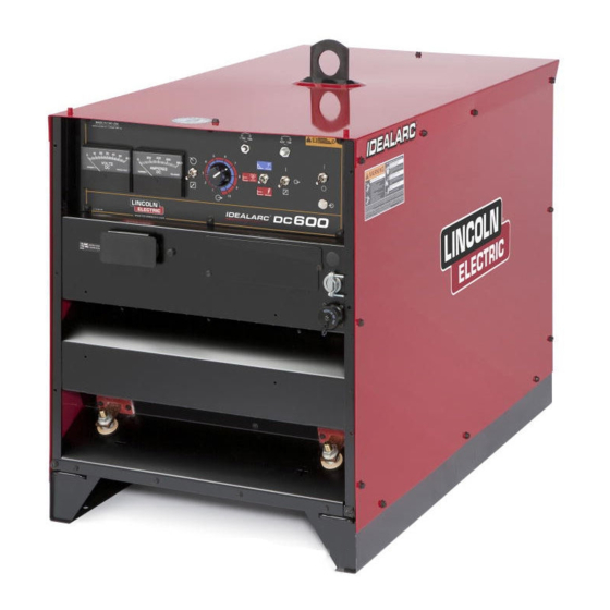
DC-600
10650
For use with machines having Code Numbers:
OPERATOR'S MANUAL
Red-D-Arc Spec-Built Welding Equipment
This RED-D-ARC welder is built to RED-D-ARC Extreme Duty
design specifications by Lincoln Electric.
Safety Depends on You
This welder is designed and built with safety in mind.
However, your overall safety can be increased by proper installation
... and thoughtful operation on your part.
DO NOT INSTALL, OPERATE OR REPAIR THIS EQUIPMENT
WITHOUT READING THIS MANUAL AND THE SAFETY
PRECAUTIONS CONTAINED THROUGHOUT.
And, most importantly, think before you act and be careful.
1-800-245-3660
North America's Largest Fleet of Welding Equipment
Advertisement
Table of Contents
Troubleshooting

Related Manuals for Red-D-Arc DC-600


Summary of Contents for Red-D-Arc DC-600
- Page 1 For use with machines having Code Numbers: OPERATOR’S MANUAL Red-D-Arc Spec-Built Welding Equipment This RED-D-ARC welder is built to RED-D-ARC Extreme Duty design specifications by Lincoln Electric. Safety Depends on You This welder is designed and built with safety in mind.
-
Page 2: California Proposition 65 Warnings
1.g. To prevent accidentally starting gasoline engines while 2.d.5. Do not work next to welding power source. turning the engine or welding generator during maintenance work, disconnect the spark plug wires, distributor cap or magneto wire as appropriate. Mar ‘95 DC-600... -
Page 3: Electric Shock Can Kill
(MSDS) and follow your employer’s safety practices. MSDS forms are available from your welding distributor or from the manufacturer. 3.j. Also see Items 6.c. and 8. 5.e. Also see item 1.b. Mar ‘95 DC-600... - Page 4 This can create fire hazards or overheat lifting chains Electrical Code, all local codes and the manufacturer’s or cables until they fail. recommendations. 6.h. Also see item 1.c. 8.c. Ground the equipment in accordance with the U.S. National Electrical Code and the manufacturer’s recommendations. Mar ‘95 DC-600...
- Page 5 4. Garder tous les couvercles et dispositifs de sûreté à leur talons sans revers, et chaussures montantes. place. 5. Toujours porter des lunettes de sécurité dans la zone de soudage. Utiliser des lunettes avec écrans lateraux dans les Mar. ‘93 DC-600...
- Page 6 This statement appears where the information must be followed exactly to avoid serious personal injury or loss of life. CAUTION This statement appears where the information must be followed to avoid minor personal injury or damage to this equipment. DC-600...
-
Page 7: Table Of Contents
Operating Steps ....................B-7 Remote Control of Machine Operation ..............B-7 Welding Procedure Recommendations ............... B-7 Semi-Automatic and Automatic Wire Feeding with a DC-600 and Wire Feeders ................B-8 NA-3 Automatic Wire Feeder ................B-8 NA-5 Automatic Wire Feeder ................B-10 LN-8 Semi-Automatic Wire Feeder ...............B-10 LN-7 &... - Page 8 TABLE OF CONTENTS Page Maintenance ....................Section D Safety Precautions ....................D-1 Routine and Periodic Maintenance................D-2 Troubleshooting ....................Section E Safety Precautions....................E-1 How to Use Troubleshooting Guide...............E-1 Troubleshooting Guide ..................E-2 Wiring Diagrams, Connection Diagrams and Dimension Prints....Section F Parts List ......................P354 Series...
-
Page 9: Installation
INSTALLATION TECHNICAL SPECIFICATIONS – DC-600 INPUT - THREE PHASE ONLY Input Current at Rated Output Standard Code 100% Duty Cycle 60% Duty Cycle 50% Duty Cycle Volatge Number 108/54/43 122/61/49 134/67/54 230/460/575/60 10650 RATED OUTPUT Duty Cycle Amps Volts at Rated Amperes... -
Page 10: Safety Precautions
Only qualified personnel should TILTING install this machine. • Turn the input power OFF at the The DC-600 must be placed on a stable, level surface disconnect switch or fuse box before so it will not topple over. working on the equipment. •... -
Page 11: Electrical Input Connections
FIGURE A.2 - Input Power Supply the Case Back of the machine near the input contac- Connections tor. Access to the Input Box Assembly is at the upper rear of the machine. See your local and national elec- trical codes for proper grounding methods. DC-600... -
Page 12: Reconnect Procedure
Reconnect Panel in the Input Box Assembly is con- nected for the proper voltage. 1. For 230/460/575, see Figure A.3. (M15666) CAUTION Failure to follow these instructions can cause immedi- ate failure of components within the machine. __________________ FIGURE A.3-Reconnect Panel Board Positions for 230/460/575 VAC Machines DC-600... -
Page 13: Output Connections
INSTALLATION OUTPUT CONNECTIONS See Table A.1 for recommended DC-600 cable sizes for combined lengths of electrode and work cables. TABLE A.1 DC-600 Cable Sizes for Combined Lengths of Copper Electrode and Work Cable at 100% Duty Cycle Cable Length Parallel Cables Cable Size Lengths up to 150 ft. -
Page 14: Auxiliary Power And Control Connections
If welding negative polarity, connect lead #21 to the “+21” connection point on the terminal strip (T.S.2). C = 2 H = 2 1 D = 4 G = 7 5 E = 7 7 F = 7 6 DC-600... -
Page 15: Operation
• Keep flammable material away. • Do not weld, cut or gouge on containers that have held combustibles. ARC RAYS can burn. • Wear eye, ear and body protection. Observe additional Safety Guidelines detailed in the beginning of this manual. DC-600... -
Page 16: General Description
OPERATION GENERAL DESCRIPTION DESIGN FEATURES AND ADVANTAGES The DC-600 is an SCR controlled three phase welding and cutting power source. It uses a single range • Excellent arc characteristics for optimum constant potentiometer to control: voltage submerged arc and Innershield welding performance. -
Page 17: Welding Capability
OPERATION WELDING CAPABILITY The DC-600 has the following Output and Duty Cycle based on operation for a 10 minute period: 600 Amps, 44 Volts at 100% 680 Amps, 44 Volts at 60% 750 Amps, 44 Volts at 50% MEANINGS OF GRAPHICAL SYMBOLS ON CASE FRONT... -
Page 18: Meaning Of Graphical Symbols On Rating Plate
Canadian Standards NRTL/C DC output Association (CSA) standards. (60 Hertz Models) Line Connection Gas Metal Arc Welding (GMAW) Flux Cored Arc Welding (FCAW) MEANING OF GRAPHICAL SYMBOL FOR GROUND CONNECTION Signifies the equipment connection point for the protective earth ground DC-600... -
Page 19: Controls And Settings
OPERATION CONTROLS AND SETTINGS All operator controls and adjustments are located on the Case Front Assembly of the DC-600. See Figure B.1 for the location of each control. FIGURE B.1 - CONTROL PANEL KEYS 1. Input POWER ON/OFF Switch 15 to 44 volts and 90 to 750 amps) as it is rotated This toggle switch turns the machine on or off. -
Page 20: Auxiliary Power In Ms-Receptacle
POWER light stays illuminated), or will operate at minimum output thus preventing any 13.Positive Output Terminal damage to the DC-600. If DC-600 shuts down, it must This output terminal is for connecting a welding be manually started by resetting the POWER ON/OFF cable. -
Page 21: Operating Steps
OPERATING STEPS REMOTE CONTROL OF MACHINE OPERATION The following procedures are for using the DC-600 in the local control mode of operation. For remote con- The toggle switch on the control panel labeled trol of the machine, see the Remote Control of “Remote - Panel”... -
Page 22: Semi-Automatic And Automatic Wire Feeding
3. Set the NA-3 mode Switch Position to either CV or voltage and then returns back to the desired volt- CC to match the DC-600 mode selected in step 2. age, the Open Circuit Voltage Control is set too high. This can result in a bad start where the wire 4. - Page 23 OPERATION ARC STRIKING WITH DC-600 AND THE NA-3 6. Establish the correct arc striking procedure with START BOARD the NA-3 Start Board timer set at maximum. When electrical strikeouts exceed 1 3/4” (44.4mm) an a. For the best starting performance, the NA-3...
-
Page 24: Ln-8 Semi-Automatic Wire Feeder
To use the LN-8 Semi-Automatic Wire Feeder with DC-600 When using the DC-600 with the NA-5 wire feeder, set the controls on the DC-600 as follows for the best per- 1. Set the DC-600 WELDING MODE SWITCH to formance: either CV INNERSHIELD mode or CV SUBMERGED ARC mode depending on the weld- 1. -
Page 25: Accessories
WIRE FEEDERS AND TRACTORS Undercarriages (K817P, K842) For easy moving of the machine, optional undercar- The DC-600 can be used to power any of the follow- riages are available with polyolefin wheels (K817P) or ing Wire Feeders and Tractors: a platform undercarriage (K842) with mountings for two gas cylinders at rear of welder. - Page 26 Support the switch in position and start cables through the strain relief loop on the left the four screws, then tighten them. side of the DC-600 (facing the front of the machine). 5. Route the MULTI-PROCESS SWITCH control leads through the strain-relief box connectors and b.
-
Page 27: Connections For Semi-Automatic Or Automatic Wire Feeder Control
3. Set the DC-600 OUTPUT TERMINALS switch to REMOTE. c. Connect the work cable to the "Negative" ter- minal on the right side of the MULTI- 4. Set the DC-600 MODE switch to the welding PROCESS SWITCH. process being used. NOTE: The instructions above are for connecting 5. -
Page 28: Maintenance
• Main transformer and choke. • Electrode and work cable connections. • SCR rectifier bridge and heat sink fins. • Control board. • Firing board. • Fan Assembly. NOTE: The fan motor has sealed bearings which require no maintenance. DC-600... -
Page 29: Troubleshooting
CAUTION If for any reason you do not understand the test procedures or are unable to perform the tests/repairs safely, contact your Local Authorized Field Service Facility for technical troubleshooting assistance before you proceed. DC-600... -
Page 30: Pc Board Troubleshooting Procedures
PC BOARDS TO VERIFY PROBLEM,” will electrically live parts at the help avoid denial of legitimate PC board war- same time. ranty claims. c. Tools which come in contact with the P.C. Board must be either conductive, anti-static or static-dis- sipative. DC-600... -
Page 31: Troubleshooting Guide
3. Power ON/OFF switch may be defective CAuTION If for any reason you do not understand the test procedures or are unable to perform the tests/repairs safely, contact your Local Authorized Field Service Facility for technical troubleshooting assistance before you proceed. Dc-600... - Page 32 1. 115VAC Circuit Breaker tripped. working. (60HZ machines only) CAUTION If for any reason you do not understand the test procedures or are unable to perform the tests/repairs safely, contact your Local Authorized Field Service Facility for technical troubleshooting assistance before you proceed. DC-600...
- Page 33 5. Trigger circuit not working. CAUTION If for any reason you do not understand the test procedures or are unable to perform the tests/repairs safely, contact your Local Authorized Field Service Facility for technical troubleshooting assistance before you proceed. DC-600...
- Page 34 Contact your local Authorized Field Service Facility. CAUTION If for any reason you do not understand the test procedures or are unable to perform the tests/repairs safely, contact your Local Authorized Field Service Facility for technical troubleshooting assistance before you proceed. DC-600...
- Page 35 3. Check for loose welding cable connections. CAUTION If for any reason you do not understand the test procedures or are unable to perform the tests/repairs safely, contact your Local Authorized Field Service Facility for technical troubleshooting assistance before you proceed. DC-600...
- Page 36 Authorized Field Ser vice OFF. Facility. CAUTION If for any reason you do not understand the test procedures or are unable to perform the tests/repairs safely, contact your Local Authorized Field Service Facility for technical troubleshooting assistance before you proceed. DC-600...
- Page 37 DC600. CAUTION If for any reason you do not understand the test procedures or are unable to perform the tests/repairs safely, contact your Local Authorized Field Service Facility for technical troubleshooting assistance before you proceed. DC-600...
-
Page 38: Welding Problems
2. Check weld cables for loose or faulty connections. Machine has output but trips off 1. Remove output cables from immediately when wire feed unit DC-600. If problem is resolved trigger is activated check for external short between weldiong cables. Also check control cable (#75, #76, &... - Page 39 3. Check the welding cables for loose or faulty connections. CAUTION If for any reason you do not understand the test procedures or are unable to perform the tests/repairs safely, contact your Local Authorized Field Service Facility for technical troubleshooting assistance before you proceed. DC-600...
- Page 40 DIAGRAMS DC-600...
- Page 41 DIAGRAMS DC-600...
- Page 42 DIAGRAMS DC-600...
- Page 43 DIAGRAMS DC-600...
- Page 44 DIAGRAMS DC-600...
- Page 45 DIAGRAMS DC-600...
- Page 46 DIAGRAMS DC-600...
- Page 47 DIAGRAMS DC-600...
- Page 48 DIAGRAMS DC-600...
- Page 49 Now Available...12th Edition New Lessons in Arc Welding The Procedure Handbook of Arc Welding Lessons, simply written, cover manipulatory techniques; With over 500,000 copies of previous editions published machine and electrode characteristics; related subjects, since 1933, the Procedure Handbook is considered by many to such as distortion;...
- Page 50 ● ● ● Do not touch electrically live parts or Keep flammable materials away. Wear eye, ear and body protection. WARNING electrode with skin or wet clothing. ● Insulate yourself from work and ground. Spanish ● ● ● No toque las partes o los electrodos Mantenga el material combustible Protéjase los ojos, los oídos y el AVISO DE...
- Page 51 ● ● ● Keep your head out of fumes. Turn power off before servicing. Do not operate with panel open or WARNING ● Use ventilation or exhaust to guards off. remove fumes from breathing zone. Spanish ● Los humos fuera de la zona de res- ●...
- Page 52 • World's Leader in Welding and Cutting Products • • Sales and Service through Subsidiaries and Distributors Worldwide • Cleveland, Ohio 44117-1199 U.S.A. TEL: 216.481.8100 FAX: 216.486.1751 WEB SITE: www.lincolnelectric.com...
Need help?
Do you have a question about the DC-600 and is the answer not in the manual?
Questions and answers