Table of Contents
Advertisement
Quick Links
IM678-A
RED-D-ARC
March, 2002
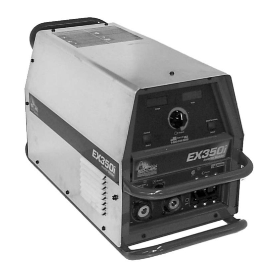
EX350i
10666; 10749
For use with machines having Code Numbers:
OPERATOR'S MANUAL
Red-D-Arc Spec-Built Welding Equipment
This RED-D-ARC welder is built to RED-D-ARC Extreme Duty
design specifications by Lincoln Electric.
Safety Depends on You
This welder is designed and built with safety in mind.
However, your overall safety can be increased by proper installation
... and thoughtful operation on your part.
DO NOT INSTALL, OPERATE OR REPAIR THIS EQUIPMENT
WITHOUT READING THIS MANUAL AND THE SAFETY
PRECAUTIONS CONTAINED THROUGHOUT.
And, most importantly, think before you act and be careful.
1-800-245-3660
North America's Largest Fleet of Welding Equipment
Advertisement
Table of Contents
Troubleshooting

Related Manuals for Red-D-Arc EX350i


Summary of Contents for Red-D-Arc EX350i
- Page 1 For use with machines having Code Numbers: OPERATOR’S MANUAL Red-D-Arc Spec-Built Welding Equipment This RED-D-ARC welder is built to RED-D-ARC Extreme Duty design specifications by Lincoln Electric. Safety Depends on You This welder is designed and built with safety in mind.
-
Page 2: California Proposition 65 Warnings
1.g. To prevent accidentally starting gasoline engines while 2.d.5. Do not work next to welding power source. turning the engine or welding generator during maintenance work, disconnect the spark plug wires, distributor cap or magneto wire as appropriate. Mar ‘95 EX350i... -
Page 3: Electric Shock Can Kill
(MSDS) and follow your yourself from a fall should you get a shock. employer’s safety practices. MSDS forms are available from your welding distributor or from the manufacturer. 3.j. Also see Items 6.c. and 8. 5.e. Also see item 1.b. Mar ‘95 EX350i... - Page 4 This can create fire hazards or overheat lifting chains Electrical Code, all local codes and the manufacturer’s or cables until they fail. recommendations. 6.h. Also see item 1.c. 8.c. Ground the equipment in accordance with the U.S. National Electrical Code and the manufacturer’s recommendations. Mar ‘95 EX350i...
- Page 5 4. Garder tous les couvercles et dispositifs de sûreté à leur talons sans revers, et chaussures montantes. place. 5. Toujours porter des lunettes de sécurité dans la zone de soudage. Utiliser des lunettes avec écrans lateraux dans les Mar. ‘93 EX350i...
- Page 6 for selecting a QUALITY product. We want you to take pride in Thank You operating this product ••• as much pride as we have in bringing this product to you! Please Examine Carton and Equipment For Damage Immediately When this equipment is shipped, title passes to the purchaser upon receipt by the carrier. Consequently, Claims for material damaged in shipment must be made by the purchaser against the transportation company at the time the shipment is received.
-
Page 7: Table Of Contents
Select Suitable Location..................A-2 Stacking ......................A-2 Tilting.......................A-2 Safety Precautions ..................A-2 Input and Grounding Connections ..............A-2 Power Cord Connection ..................A-2 Connection of Wire Feeders to EX350i............A-2 Remote Control of EX350i ................A-3 Undercarriage Mountings................A-3 Parallel Operations..................A-4 Quick Disconnect Plugs ..................A-4 ________________________________________________________________________ Operation ......................Section B Additional Safety Precautions ................B-1... -
Page 8: Installation
1 & 3 Phase 275A / 31V / 100% (36.9 kg) 60/50 Hz * Overall Length Including Handle, 27.8” (706mm). EX350i INPUT CURRENT Recommended Fuse Sizes Based On The U.S. National Electrical Code And Maximum Machine Outputs Input 50/60 Hz Output Recommended... -
Page 9: Select Suitable Location
14 pin amphenol. The not place on wet ground or in puddles. 42 Volt Remote Voltage and Output Control (K624- 1) Kit can be connected to the EX350i 24/42 VAC Stacking amphenol using Remote Control Cable assembly EX350i cannot be stacked. -
Page 10: Undercarriage Mountings
Wire feeders other than LN-7 and LN-25 may be used • Set the meter polarity switch on the front of the EX350i to provided that the auxiliary power supply capacity of coincide with wire feeder polarity used. -
Page 11: Parallel Operations
INSTALLATION PARALLEL OPERATION The EX350i are operable in parallel in CC mode. For best results, the currents of each machine should be reasonably well shared. As an example, with two machines set up in parallel for a 400 amp procedure,... -
Page 12: Operation
• Output control is conducted via a single turn poten- tiometer. • Adjustment is indicated by the meters as stated The EX350i offers multi mode CV and CC DC welding above. and is rated 350 amps, 34 volts at a 60% duty cycle. - Page 13 SELECT SELECT SELECT SELECT WELD MODE WELD MODE HOT ST T STAR ARC CONTR ARC CONTROL CC-STICK SOFT CC-STICK CRISP TIG GTAW CV-WIRE SELECT CV-FLUX CORED SOFT SOFT CRISP CRISP OF F OF F O F F O FF EX350i...
-
Page 14: Remote Control Of The Output Control And Weld Terminals
• The Arc Control is not used in the TIG mode. EX350i is not configured the way you would like the local or remote control settings can be changed by CV-WIRE: The CV-WIRE mode features continuous pushing the OUTPUT CONTROL or WELD TERMI- control from 10 to 45 volts. -
Page 15: Design Features And Advantages
EX350i or the welding output) The supply should be capable of supplying at least 20mA. • 0 volts supplied to 76 will set the EX350i to mini- mum output for the mode that has been selected while 10 volts supplied to 76 will set the EX350i to the maximum output for the mode. -
Page 16: Auxiliary Power
6 amp breaker located by the amphenol. LIMITATIONS • The EX350i is not recommended for processes other than those listed. • The EX350i can only be used with the recommend- ed equipment and options. RECOMMENDED PROCESSES Properly equipped, the EX350i supports GMAW,... -
Page 17: Accessories
ACCESSORIES OPTIONS / ACCESSORIES • The EX350i provides the hardware to power and con- nect to 24, 42 or 115 VAC wire feeders. K857 Remote Output Control K814 Arc Start Switch K812 Hand Operated Amptrol K870 Foot Operated Amptrol K930-1... -
Page 18: Maintenance
Thermostats are self-resetting once the machine cools sufficiently. If the thermostat shutdown was caused by excessive output or duty cycle and the fan is operating normally, the Power Switch may be left on and the reset should occur within a 15 minute period. EX350i... -
Page 19: How To Use Troubleshooting Guide
CAUTION If for any reason you do not understand the test procedures or are unable to perform the tests/repairs safely, contact your Local Authorized Field Service Facility for technical troubleshooting assistance before you proceed. EX350i... -
Page 20: Troubleshooting
CAUTION If for any reason you do not understand the test procedures or are unable to perform the tests/repairs safely, contact your Local Authorized Field Service Facility for technical troubleshooting assistance before you proceed. EX350i... - Page 21 Contact your local Authorized Field Service Facility. CAUTION If for any reason you do not understand the test procedures or are unable to perform the tests/repairs safely, contact your Local Authorized Field Service Facility for technical troubleshooting assistance before you proceed. EX350i...
-
Page 22: Fault Codes
Shop mode CAUTION If for any reason you do not understand the test procedures or are unable to perform the tests/repairs safely, contact your Local Authorized Field Service Facility for technical troubleshooting assistance before you proceed. EX350i... -
Page 23: Displays
5 second period, the display will revert to the above mode. CAUTION If for any reason you do not understand the test procedures or are unable to perform the tests/repairs safely, contact your Local Authorized Field Service Facility for technical troubleshooting assistance before you proceed. EX350i... - Page 24 DIAGRAMS EX350i...
- Page 25 DIAGRAMS EX350i...
- Page 26 DIAGRAMS EX350i...
- Page 27 DIAGRAMS EX350i...
- Page 28 DIAGRAMS EX350i...
- Page 29 DIAGRAMS EX350i...
- Page 30 DIAGRAMS xxxxxxx EX350i...
- Page 31 DIAGRAMS EX350i...
- Page 32 NOTES EX350i...
- Page 33 ● ● ● Do not touch electrically live parts or Keep flammable materials away. Wear eye, ear and body protection. WARNING electrode with skin or wet clothing. ● Insulate yourself from work and ground. Spanish ● ● ● No toque las partes o los electrodos Mantenga el material combustible Protéjase los ojos, los oídos y el AVISO DE...
- Page 34 ● ● ● Keep your head out of fumes. Turn power off before servicing. Do not operate with panel open or WARNING ● Use ventilation or exhaust to guards off. remove fumes from breathing zone. Spanish ● Los humos fuera de la zona de res- ●...
- Page 35 • World's Leader in Welding and Cutting Products • • Sales and Service through Subsidiaries and Distributors Worldwide • Cleveland, Ohio 44117-1199 U.S.A. TEL: 216.481.8100 FAX: 216.486.1751 WEB SITE: www.lincolnelectric.com...
Need help?
Do you have a question about the EX350i and is the answer not in the manual?
Questions and answers