
Related Manuals for Midea MOBA30U-12HN1-Q


Summary of Contents for Midea MOBA30U-12HN1-Q
-
Page 1: Table Of Contents
DM17-01.01.08en Light Commercial 50Hz R410A ON/OFF SERIES Service Manual 2017 Outdoor units: Indoor units: MOBA30U-12HN1-Q MHG-24HWN1-Q1 MCA3-12HRN1-Q1 MOBA30U-18HN1-Q MHG-36HWN1-R1 MCA3-18HRN1-Q1 MOCA30U-24HN1-Q MHG-48HWN1-R MOD31U-36HN1-R MCD-18HRN1-Q1 MHG-60HWN1-R MOU-48HN1-R MCD-24HRN1-Q1 MOUA-60HN1-R MUE-12HRN1-Q1 MCD-36HRN1-R1 MUE-18HRN1-Q1 MCD-48HRN1-R MCD-60HRN1-R MUE-24HRN1-Q1 MUE-36HRN1-R1 MTB-18HWN1-Q1 MUE-48HRN1-R MUE-60HRN1-R MTB-24HWN1-Q1 MTI-36HWN1-R1... -
Page 2: Part 1 General Information
Light Commercial R410A on-off DM17-01.01.08en Part 1 General Information ............ 3 Part 2 Indoor Units ..............9 Part 3 Outdoor Units ............116 Part 4 Installation ...............130 Part 5 Electrical Control System ........168 ※The specifications, designs, and information in this book are subject to change without notice for product improvement. -
Page 3: Part 1 General Information
Light Commercial R410A on-off DM17-01.01.08en Part 1 General Information 1. Model Lists ................4 2. External Appearance ............. 5 3. Nomenclature ................. 7... -
Page 4: Model Lists
Cooling and heating ● ● ● M Floor-standing Cooling and heating 1.2 Outdoor Units Universal Outdoor unit Model Compressor type Compressor Brand Matched indoor units Heat Pump MCA3-12HRN1-Q1 MOBA30U-12HN1-Q ROTARY GMCC MUE-12HRN1-Q1 MCA3-18HRN1-Q1 MUE-18HRN1-Q1 MOBA30U-18HN1-Q ROTARY GMCC MTB-18HWN1-Q1 MCD-18HRN1-Q1 MFM-24ARN1-Q MUE-24HRN1-Q1... -
Page 5: External Appearance
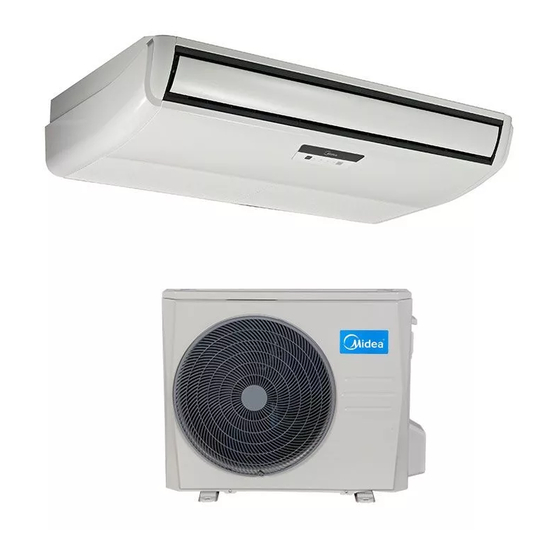
Light Commercial R410A on-off DM17-01.01.08en 2. External Appearance 2.1 Indoor Units Compact Four-way cassette Super-slim 4-way Cassette Middle static pressure duct Middle static pressure duct High static pressure duct Ceiling & floor type M Floor-standing... - Page 6 DM17-01.01.08en Light Commercial R410A on-off 2.2 Outdoor Units Single fan outdoor unit Double fan outdoor unit...
-
Page 7: Nomenclature
M U B ‐ 36 H R N1 ‐ Q 1 Minor constructive changes Power supply Q 220~240V, 1N, 50Hz R 380~420V, 3N, 50Hz Refrigerant N1 R410A ‐‐ R22 Control Mode W Wired control R Remote control Function Code C Cooling Only H Cooling&Heating A Cooling&Heating+PTC Capacity (x1000 Btu/h) Design Time A Time A Designed B Time B Designed C Time C Designed D Time D Designed Product Category C Cassette Type T Duct Type U Ceiling&Floor Type H HSP Duct Type Midea... -
Page 8: Outdoor Unit
DM17-01.01.08en Light Commercial R410A on-off 3.2 Outdoor Unit M O D30 U ‐ 36 H N1 ‐ Q Power supply Q 220~240V, 1N, 50Hz R 380~420V, 3N, 50Hz Refrigerant N1 R410A ‐‐ R22 Function Code C Cooling Only H Cooling&Heating A Cooling&Heating+PTC Capacity (x1000 Btu/h) U Side Discharge Outdoor Unit Outdoor Size Code Product Category O Outdoor unit Midea... - Page 9 Light Commercial R410A on-off DM17-01.01.08en Part 2 Indoor Units Four-way Cassette Type (Compact) ......... 10 Four-way Cassette Type ............. 23 MSP Duct Type ..............43 HSP Duct Type ..............65 Ceiling & Floor Type ............86 ...
- Page 10 DM17-01.01.08en Light Commercial R410A on-off Four-way Cassette Type (Compact) Features ................11 Specification ..............12 Dimensions ................ 12 Service Space ..............14 Capacity tables ..............14 Air Velocity and Temperature Distributions ....15 Wiring Diagrams ..............18 Electric Characteristics ............. 19 Sound Levels ..............
-
Page 11: Features
Light Commercial R410A on-off DM17-01.01.08en Features 1.1 Compact design The body size is 570×260×570mm, it’s just smaller than the ceiling board, so it’s very easy for installation and will not damage the decoration. The panel size is 647×50×647mm. The hooks are designed in the four corners of the body, which can save installation space. -
Page 12: Specification
DM17-01.01.08en Light Commercial R410A on-off Specification Indoor model MCA3-12HRN1-Q1 MCA3-18HRN1-Q1 Outdoor model MOBA30U-12HN1-Q MOBA30U-18HN1-Q Power supply V-ph-Hz 220~240-1-50 220~240-1-50 Btu/h 12500 18300 Capacity 3,66 5,36 Cooling Input 1350 1980 Current 8,78 2,71 2,71 Btu/h 13000 19000 Capacity 3,81 5,57 Heating... -
Page 13: Dimensions
Light Commercial R410A on-off DM17-01.01.08en Dimensions... -
Page 14: Service Space
DM17-01.01.08en Light Commercial R410A on-off Service Space... -
Page 15: Capacity Tables
Light Commercial R410A on-off DM17-01.01.08en Capacity tables 5.1 MCA3-12HRN1-Q1 / MOBA30U-12HN1-Q COOLING OUTDOOR TEMPERATURE DRY Indoor 21ºC 25ºC 30ºC 35ºC 40ºC 45ºC Conditions Total capacity kW 3,39 3,36 3,32 3,26 2,61 2,44 21ºC D Sensitive capacity kW 2,71 2,68 ... - Page 16 DM17-01.01.08en Light Commercial R410A on-off 5.2. MCA3-18HRN1-Q1 / MOBA30U-18HN1-Q COOLING OUTDOOR TEMPERATURE DRY Indoor 21ºC 25ºC 30ºC 35ºC 40ºC 45ºC Conditions Total capacity kW 4,96 4,91 4,87 4,77 3,82 3,58 21ºC D Sensitive capacity kW 3,97 3,93 3,89 3,82 ...
-
Page 17: Air Velocity And Temperature Distributions
Light Commercial R410A on-off DM17-01.01.08en Air Velocity and Temperature Distributions(Reference Data) Airflow velocity Temperature... -
Page 18: Wiring Diagrams
DM17-01.01.08en Light Commercial R410A on-off Wiring Diagrams MCA3-12HRN1-Q1, MCA3-18HRN1-Q1... -
Page 19: Electric Characteristics
Light Commercial R410A on-off DM17-01.01.08en Electric Characteristics Indoor Units Power Supply Model Voltage Min. Max. MCA3-12HRN1-Q1 220-240V 198V 254V MCA3-18HRN1-Q1 220-240V 198V 254V Note: MFA: Max. Fuse Amps. (A) -
Page 20: Sound Levels
DM17-01.01.08en Light Commercial R410A on-off Sound Levels 1.4m Microphone Noise level dB(A) Model MCA3-12HRN1-Q1 MCA3-18HRN1-Q1... -
Page 21: The Specification Of Power
Light Commercial R410A on-off DM17-01.01.08en The Specification of Power MCA3-12HRN1-Q1 Type MCA3-18HRN1-Q1 Phase 1-phase Power Frequency and Voltage 220-240V, 50Hz 20/16 Circuit Breaker/ Fuse (A) 3×2.5 Indoor Unit Power Wiring (mm Ground Wiring 3×2.5 Outdoor Unit Power Wiring Indoor/Outdoor Connecting Wiring Strong Electric Signal 2×1.0... -
Page 22: Field Wiring
DM17-01.01.08en Light Commercial R410A on-off Field Wiring... -
Page 23: Four-Way Cassette Type
Light Commercial R410A on-off DM17-01.01.08en Four-way Cassette Type 1. Features ................24 2. Specification ..............26 3. Dimensions ..............26 4. Service Space ..............29 5. Capacity tables ..............30 6. Wiring Diagrams ............. 35 7. Electric Characteristics ..........38 8. -
Page 24: Features
DM17-01.01.08en Light Commercial R410A on-off 1. Features 1.1 Overview Compact design, super slim body size, less space requiring in installation Each louver can be separately controlled, more comfort air blowing is possible. Fresh air intake function Fresh air fulfills air quality more healthy and comfortable. ... - Page 25 Light Commercial R410A on-off DM17-01.01.08en Built-in draining pump Due to the improvement of structure, more convenient to repair or replace the draining pump. Draining Pump Built-in draining pump to make sure condensed water drain out reliably. 1.5 Terminals for alarm lamp and long-distance on-off controller connection are standard Reserve terminals for the connection of alarm lamp and long-distance on-off controller, more human ...
-
Page 26: Indoor Units
DM17-01.01.08en Light Commercial R410A on-off 2. Specification Indoor model MCD-18HRN1-Q1 MCD-24HRN1-Q1 Outdoor model MOBA30U-18HN1-Q MOCA30U-24HN1-Q Power supply V-ph-Hz 220-240-1-50 220-240-1-50 Btu/h 18000 24000 Capacity 5,28 7,03 Cooling Input 1990 2600 Current 8.82 12.48 2,65 2,71 Btu/h 19000 26000 Capacity 5,57 7,62 Heating Input... - Page 27 Light Commercial R410A on-off DM17-01.01.08en Indoor model MCD-36HRN1-R1 MCD-48HRN1-R MCD-60HRN1-R Outdoor model MOD31U-36HN1-R MOU-48HN1-R MOUA-60HN1-R Power supply V,Hz,Ph 380~415,50,3 380~415,50,3 380~415,50,3 Capacity Btu/h 36000 48000 55000 Input 3600 5191 6272 Cooling Current 2,93 2.71 2.57 Capacity Btu/h 36000 52000 61000 Input 3650 4763...
-
Page 28: Dimensions
DM17-01.01.08en Light Commercial R410A on-off 3. Dimensions 92 92 Fresh air intake 4-install hanger Body Gas side Liquid side Wiring connection port E-parts box Service hole for Test mouth & Test cover draining pump Drain hole 92 92 92 92 Panel Unit: mm Model... -
Page 29: Service Space
Light Commercial R410A on-off DM17-01.01.08en 4. Service Space >1000mm >1000mm... -
Page 30: Capacity Tables
DM17-01.01.08en Light Commercial R410A on-off 5. Capacity tables 5.1. MCD-18HRN1-Q1 / MOBA30U-18HN1-Q COOLING OUTDOOR TEMPERATURE DRY Indoor 21ºC 25ºC 30ºC 35ºC 40ºC 45ºC Conditions Total capacity kW 6,51 6,44 6,38 6,26 5,01 4,69 21ºC D Sensitive capacity kW 5,21 5,16 ... - Page 31 Light Commercial R410A on-off DM17-01.01.08en 5.2. MCD-24HRN1-Q1 / MOCA30U-24HN1-Q COOLING OUTDOOR TEMPERATURE DRY Indoor 21ºC 25ºC 30ºC 35ºC 40ºC 45ºC Conditions Total capacity kW 4,96 4,91 4,87 4,77 3,82 3,58 21ºC D Sensitive capacity kW 3,97 3,93 3,89 3,82 ...
- Page 32 DM17-01.01.08en Light Commercial R410A on-off 5.3. MCD-36HRN1-R1 / MOD31U-36HN1-R COOLING OUTDOOR TEMPERATURE DRY Indoor 21ºC 25ºC 30ºC 35ºC 40ºC 45ºC Conditions Total capacity kW 9,77 9,67 9,58 9,39 7,51 7,04 21ºC D Sensitive capacity kW 7,81 7,74 ...
- Page 33 Light Commercial R410A on-off DM17-01.01.08en 5.4. MCD-48HRN1-R / MOU-48HN1-R COOLING OUTDOOR TEMPERATURE DRY Indoor 21ºC 25ºC 30ºC 35ºC 40ºC 45ºC Conditions Total capacity kW 13,02 12,90 12,77 12,52 10,02 9,39 21ºC D Sensitive capacity kW 10,42 10,32 10,22 10,02 ...
- Page 34 DM17-01.01.08en Light Commercial R410A on-off 5.5. MCD-60HRN1-R / MOUA-60HN1-R COOLING OUTDOOR TEMPERATURE DRY Indoor 21ºC 25ºC 30ºC 35ºC 40ºC 45ºC Conditions Total capacity kW 14,92 14,78 14,63 14,35 11,48 10,76 21ºC D Sensitive capacity kW 11,94 11,82 11,71 11,48 ...
-
Page 35: Mcd-18Hrn1-Q1
Light Commercial R410A on-off DM17-01.01.08en 6. Wiring Diagrams MCD-18HRN1-Q1 MCD-24HRN1-Q1... -
Page 36: Mcd-36Hrn1-R1
DM17-01.01.08en Light Commercial R410A on-off MCD-36HRN1-R1... -
Page 37: Mcd-48Hrn1-Rmcd-60Hrn1-R
Light Commercial R410A on-off DM17-01.01.08en MCD-48HRN1-R, MCD-60HRN1-R... -
Page 38: Electric Characteristics
DM17-01.01.08en Light Commercial R410A on-off 7. Electric Characteristics Indoor Unit Power Supply Model Voltage MCD-18HRN1-Q1 220-240V 198V 254V MCD-24HRN1-Q1 220-240V 198V 254V MCD-36HRN1-R1 220-240V 198V 254V MCD-48HRN1-R 380-415V 342V 436V MCD-60HRN1-R 380-415V 342V 436V Notes: MFA: Max. Fuse Amps. (A) -
Page 39: Sound Levels
Light Commercial R410A on-off DM17-01.01.08en 8. Sound Levels 1.4m Microphone Noise level dB(A) Model MCD-18HRN1-Q1 MCD-24HRN1-Q1 MCD-36HRN1-R1 MCD-48HRN1-R MCD-60HRN1-R... -
Page 40: The Specification Of Power
DM17-01.01.08en Light Commercial R410A on-off 9. The Specification of Power Model (KBtu/h) 48~60 Phase 1-phase 1-phase 3-phase 3-phase Power Frequency and Voltage 220-240V, 50Hz 380-415V, 50Hz Circuit Breaker/ Fuse (A) 25/20 32/25 25/20 32/25 Indoor Unit Power Wiring (mm 3×2.5 3×2.5 3×1.5 5×2.5... -
Page 41: Field Wiring
Light Commercial R410A on-off DM17-01.01.08en 10. Field Wiring MCD-18HRN1-Q1 MCD-24HRN1-Q1... - Page 42 DM17-01.01.08en Light Commercial R410A on-off MCD-36HRN1-R1 MCD-48HRN1-R, MCD-60HRN1-R...
-
Page 43: Msp Duct Type
Light Commercial R410A on-off DM17-01.01.08en MSP Duct Type 1. Features ................44 2. Specification ..............46 3. Dimensions ..............46 4. Service Space ..............49 5. Capacity tables ..............50 6. Wiring Diagrams ............. 55 7. Static Pressure ..............57 8. -
Page 44: Features
DM17-01.01.08en Light Commercial R410A on-off 1. Features 1.1 Easy Installation: Two air inlet styles (Bottom side or Rear side) Air inlet from rear is standard for all capacity; air inlet from bottom is optional. The size of air inlet frame from rear and bottom is same, it’s very easy to move the cover from bottom to ... - Page 45 Light Commercial R410A on-off DM17-01.01.08en 1.4 Reserved remote on-off and central control ports Reserved remote on-off ports and central control ports, can connect the cable of an on-off controller or a central controller to realize remote on-off control function or group control function. Remote on-off ports Central control ports 1.4 Built-in display board...
-
Page 46: Specification
DM17-01.01.08en Light Commercial R410A on-off 2. Specification Indoor model MTB-18HWN1-Q1 MTB-24HWN1-Q1 Outdoor model MOBA30U-18HN1-Q MOCA30U-24HN1-Q Power supply V-ph-Hz 220-240-1-50 220-240-1-50 Btu/h 18000 24000 Capacity 5.28 7.03 Cooling Input 2130 2650 Current 8,82 12,72 2,48 2,65 Btu/h 19000 26000 Capacity 5.57 7.62 Heating Input... - Page 47 Light Commercial R410A on-off DM17-01.01.08en Indoor model MTI-36HWN1-R1 MTB-48HWN1-R MTB-60HWN1-R Outdoor model MOD31U-36HN1-R MOU-48HN1-R MOUA-60HN1-R Power supply V,Hz,Ph 380~415,50,3 380~420,50,3 380~420,50,3 Capacity Btu/h 36000 48000 55000 Input 3654 5240 6225 Cooling Current 6.12 7,60 10,90 2,89 2,68 2,59 Capacity Btu/h 37000 55000 60000...
-
Page 48: Dimensions
DM17-01.01.08en Light Commercial R410A on-off 3. Dimensions air inlet from rear side Air filter ( optional ) 4-install hanger Liquid side 25 Drain pipe Gas side 25 Drain pipe Test mouth & Test cover 25 Drain connecting pipe ( for pump ) Fresh air intake Electric control box Air filter ( optional ) -
Page 49: Service Space
Light Commercial R410A on-off DM17-01.01.08en 4. Service Space Ensure enough space required for installation and maintenance. -
Page 50: Capacity Tables
DM17-01.01.08en Light Commercial R410A on-off 5. Capacity tables 5.1. MTB-18HWN1-Q1 / MOBA30U-18HN1-Q COOLING OUTDOOR TEMPERATURE DRY Indoor 21ºC 25ºC 30ºC 35ºC 40ºC 45ºC Conditions Total capacity kW 4,89 4,84 4,79 4,70 3,76 3,52 21ºC D Sensitive capacity kW 3,91 3,87 ... - Page 51 Light Commercial R410A on-off DM17-01.01.08en 5.2. MTB-24HWN1-Q1 / MOCA30U-24HN1-Q COOLING OUTDOOR TEMPERATURE DRY Indoor 21ºC 25ºC 30ºC 35ºC 40ºC 45ºC Conditions Total capacity kW 6,51 6,44 6,38 6,26 5,01 4,69 21ºC D Sensitive capacity kW 5,21 5,16 5,11 5,01 ...
- Page 52 DM17-01.01.08en Light Commercial R410A on-off 5.3. MTI-36HWN1-R1 / MOD31U-36HN1-R COOLING OUTDOOR TEMPERATURE DRY Indoor 21ºC 25ºC 30ºC 35ºC 40ºC 45ºC Conditions Total capacity kW 9,77 9,67 9,58 9,39 7,51 7,04 21ºC D Sensitive capacity kW 7,81 7,74 ...
- Page 53 Light Commercial R410A on-off DM17-01.01.08en 5.4. MTB-48HWN1-R / MOU-48HN1-R COOLING OUTDOOR TEMPERATURE DRY Indoor 21ºC 25ºC 30ºC 35ºC 40ºC 45ºC Conditions Total capacity kW 13,02 12,90 12,77 12,52 10,02 9,39 21ºC D Sensitive capacity kW 10,42 10,32 10,22 10,02 ...
- Page 54 DM17-01.01.08en Light Commercial R410A on-off 5.5. MTB-60HWN1-R / MOUA-60HN1-R COOLING OUTDOOR TEMPERATURE DRY Indoor 21ºC 25ºC 30ºC 35ºC 40ºC 45ºC Conditions Total capacity kW 14,92 14,78 14,63 14,35 11,48 10,76 21ºC D Sensitive capacity kW 11,94 11,82 11,71 11,48 ...
-
Page 55: Mtb-18Hwn1-Q1
Light Commercial R410A on-off DM17-01.01.08en 6. Wiring Diagrams MTB-18HWN1-Q1 MTB-24HWN1-Q1... -
Page 56: Mti-36Hwn1-R1
DM17-01.01.08en Light Commercial R410A on-off MTI-36HWN1-R1 MTB-48HWN1-R, MTB-60HWN1-R... -
Page 57: Static Pressure
Light Commercial R410A on-off DM17-01.01.08en 7. Static Pressure 1200 1000 External static pressure (Pa) 1600 1400 1200 1000 External static pressure (Pa) - Page 58 DM17-01.01.08en Light Commercial R410A on-off 2000 1800 1600 1400 1200 1000 External Static Pressure (Pa) 3000 2500 2000 1500 1000 External static pressure (Pa)
- Page 59 Light Commercial R410A on-off DM17-01.01.08en 3000 2500 2000 1500 1000 External static pressure (Pa)
-
Page 60: Electric Characteristics
DM17-01.01.08en Light Commercial R410A on-off lectric Characteristics Indoor Units Power Supply Model Voltage Min. Max. MTB-18HWN1-Q1 220-240V 198V 254V MTB-24HWN1-Q1 220-240V 198V 254V MTI-36HWN1-R1 220-240V 198V 254V MTB-48HWN1-R 380-415V 342V 436V MTB-60HWN1-R 380-415V 342V 436V Notes: MFA: Max. Fuse Amps. (A) -
Page 61: Sound Levels
Light Commercial R410A on-off DM17-01.01.08en 9. Sound Levels Concealed Duct Type Discharge Suction Duct Duct 1.4m Microphone Noise level dB(A) Model MTB-18HWN1-Q MTB-24HWN1-Q MTI-36HWN1-R1 MTB-48HWN1-R MTB-60HWN1-R... -
Page 62: The Specification Of Power
DM17-01.01.08en Light Commercial R410A on-off 10. The Specification of Power Model (KBtu/h) 48~60 Phase 1-phase 1-phase 3-phase 3-phase Power Frequency and Voltage 220-240V, 50Hz 380-415V, 50Hz 380-415V, 50Hz 25/20 Circuit Breaker/ Fuse (A) 25/20 32/25 32/25 3×1.5 Indoor Unit Power Wiring (mm 3×2.5 3×2.5 5×2.5... -
Page 63: Field Wiring
Light Commercial R410A on-off DM17-01.01.08en 11. Field Wiring MTB-18HWN1-Q1 MTB-24HWN1-Q1... - Page 64 DM17-01.01.08en Light Commercial R410A on-off MTI-36HWN1-R MTB-48HWN1-R, MTB-60HWN1-R...
-
Page 65: Hsp Duct Type
Light Commercial R410A on-off DM17-01.01.08en HSP Duct Type 1. Features ................66 2. Specification ..............68 3. Dimensions ..............70 4. Service Space ..............71 5. Capacity tables ..............72 6. Wiring Diagrams ............. 76 7. Static Pressure ..............80 8. -
Page 66: Features
DM17-01.01.08en Light Commercial R410A on-off Features 1.1 High static pressure design Max static pressure of indoor unit is 160Pa. The longest distance of air supply is 14m, the max height of air supply is 6.5m. Specially recommended for spacious and large rooms like large stores and factories. High static pressure design enables long duct. - Page 67 Light Commercial R410A on-off DM17-01.01.08en 1.4 Easy cleaning filter The filter can be easily removed or installed from the rear side for ease of cleaning.
-
Page 68: Specification
DM17-01.01.08en Light Commercial R410A on-off 2. Specification Indoor Model MHG-24HWN1-Q1 Outdoor Model MOCA30U-24HN1-Q Power supply V- Ph-Hz 220-240-1-50 Btu/h 24000 Capacity 7.03 Cooling Input 2710 Current 13,01 2,60 Btu/h 26000 Capacity 7.62 Heating Input 2270 Current 10,89 3,36 Model YKSS-115-4-20 Indoor fan motor Input 228/180/155... - Page 69 Light Commercial R410A on-off DM17-01.01.08en Indoor Model MHG-36HWN1-R1 MHG-48HWN1-R MHG-60HWN1-R Outdoor Model MOD31U-36HN1-R MOU-48HN1-R MOUA-60HN1-R Power supply V,Hz,Ph 380~420,50,3 380~420,50,3 380-415,50,3 Capacity Btu/h 36000 49000 56000 Input 3750 5128 6500 Cooling Current 11,2 2,81 2,53 Capacity Btu/h 36000 52000 62000 Input 3300 4220...
-
Page 70: Dimensions
DM17-01.01.08en Light Commercial R410A on-off 3. Dimensions Unit: mm Capacity Size of Outline dimension Air outlet opening size Air inlet opening size (KBtu) mounted lug 1110 1146 1054 1061 48/60 1200 1236 1000 1145... -
Page 71: Service Space
Light Commercial R410A on-off DM17-01.01.08en 4. Service Space Ensure enough space required for installation and maintenance. 500mm or more 600mm or more Indoor unit Maintenance and repair space 600mmx600mm... -
Page 72: Capacity Tables
DM17-01.01.08en Light Commercial R410A on-off Capacity tables 5.1. MHG-24HWN1-Q1 / MOCA30U-24HN1-Q COOLING OUTDOOR TEMPERATURE DRY Indoor 21ºC 25ºC 30ºC 35ºC 40ºC 45ºC Conditions Total capacity kW 6,51 6,44 6,38 6,26 5,01 4,69 21ºC D Sensitive capacity kW 5,21 5,16 5,11 ... - Page 73 Light Commercial R410A on-off DM17-01.01.08en 5.2. MHG-36HWN1-R1 / MOD31U-36HN1-R COOLING OUTDOOR TEMPERATURE DRY Indoor 21ºC 25ºC 30ºC 35ºC 40ºC 45ºC Conditions Total capacity kW 9,77 9,67 9,58 9,39 7,51 7,04 21ºC D Sensitive capacity kW 7,81 7,74 ...
- Page 74 DM17-01.01.08en Light Commercial R410A on-off 5.3. MHG-48HWN1-R / MOU-48HN1-R COOLING OUTDOOR TEMPERATURE DRY Indoor 21ºC 25ºC 30ºC 35ºC 40ºC 45ºC Conditions Total capacity kW 13,29 13,16 13,04 12,78 10,23 9,59 21ºC D Sensitive capacity kW 10,63 10,53 ...
- Page 75 Light Commercial R410A on-off DM17-01.01.08en 5.4. MHG-60HWN1-R / MOUA-60HN1-R COOLING OUTDOOR TEMPERATURE DRY Indoor 21ºC 25ºC 30ºC 35ºC 40ºC 45ºC Conditions Total capacity kW 15,19 15,05 14,90 14,61 11,69 10,96 21ºC D Sensitive capacity kW 12,15 12,04 ...
-
Page 76: Mhg-24Hwn1-Q1
DM17-01.01.08en Light Commercial R410A on-off Wiring Diagrams MHG-24HWN1-Q1... -
Page 77: Mhg-36Hwn1-R1
Light Commercial R410A on-off DM17-01.01.08en MHG-36HWN1-R1... -
Page 78: Mhg-48Hwn1-R
DM17-01.01.08en Light Commercial R410A on-off MHG-48HWN1-R... -
Page 79: Mhg-60Hwn1-R
Light Commercial R410A on-off DM17-01.01.08en MHG-60HWN1-R... -
Page 80: Static Pressure
DM17-01.01.08en Light Commercial R410A on-off 7. Static Pressure 1800 1600 1400 1200 1000 External static pressure (Pa) 2500 2000 1500 1000 100 110 120 130 140 150 External static pressure (Pa) 48/60K 4000 3500 3000 2500 2000 1500 1000 0 10 20 30 40 50 60 70 80 90 100 110 120 130 140 150 160 170 180 190 200 External static pressure (Pa) -
Page 81: Electric Characteristics
Light Commercial R410A on-off DM17-01.01.08en 8. Electric Characteristics Indoor Unit Power Supply Model Voltage Min. Max. MHG-24HWN1-Q1 220-240V 198V 254V MHG-36HWN1-R1 220-240V 198V 254V MHG-48HWN1-R 380-415V 342V 436V MHG-60HWN1-R 380-415V 342V 436V Notes: MFA: Max. Fuse Amps. (A) -
Page 82: Sound Levels
DM17-01.01.08en Light Commercial R410A on-off 9. Sound Levels Concealed Duct Type Discharge Suction Duct Duct 1.5m Microphone Noise level dB(A) Model MHG-24HWN1-Q1 MHG-36HWN1-R1 MHG-48HWN1-R MHG-60HWN1-R... -
Page 83: The Specification Of Power
Light Commercial R410A on-off DM17-01.01.08en 10. The Specification of Power Model (KBtu/h) 48~60 Phase 1-phase 3-phase 3-phase Power 220-240V, Frequency and Voltage 380-415V, 50Hz 380-415V, 50Hz 50Hz Circuit Breaker/ Fuse (A) 32/25 25/20 32/25 Indoor Unit Power Wiring (mm 3×2.5 3×1.5 5×2.5 Ground Wiring... -
Page 84: Field Wiring
DM17-01.01.08en Light Commercial R410A on-off 11. Field Wiring MHG-24HWN1-Q1 MHG-36HWN1-R1... - Page 85 Light Commercial R410A on-off DM17-01.01.08en MHG-48HWN1-R, MHG-60HWN1-R...
-
Page 86: Ceiling & Floor Type
DM17-01.01.08en Light Commercial R410A on-off Ceiling & Floor Type 1. Features ................87 2. Specification ..............88 3. Dimensions ..............90 4. Service Space ..............91 5. Capacity tables ..............92 6. Wiring Diagram ............... 98 7. Electric Characteristics ..........100 8. -
Page 87: Features
Light Commercial R410A on-off DM17-01.01.08en Features 1.1. New design, more modern and elegant appearance. 1.2. Convenient installation --The ceiling type can be easily installed into a corner of the ceiling even if the ceiling is very narrow --It is especially useful when installation of an air conditioner in the center of the ceiling is impossible due to a structure such as one lighting. -
Page 88: Mue-12Hrn1-Q1
DM17-01.01.08en Light Commercial R410A on-off Specification Indoor Model MUE-12HRN1-Q1 MUE-18HRN1-Q1 MUE-24HRN1-Q1 Outdoor Model MOBA30U-12HN1-Q MOBA30U-18HN1-Q MOCA30U-24HN1-Q Power supply V-ph-Hz 220~240-1-50 220~240-1-50 220~240-1-50 Btu/h 12500 18500 24000 Capacity 3.66 5.42 7.03 Cooling Input 1350 2110 2630 Current 9.36 12.62 2,71 2,57... - Page 89 Light Commercial R410A on-off DM17-01.01.08en Indoor Model MUE-36HRN1-R1 MUE-48HRN1-R MUE-60HRN1-R Outdoor Model MOD31U-36HN1-R MOU-48HN1-R MOUA-60HN1-R Power supply V-ph-Hz 380~415-3-50 380~415-3-50 380~415-3-50 Capacity Btu/h 36000 48000 55000 Input 3600 5060 6400 Cooling Current 10.5 2,93 2,78 2.52 Capacity Btu/h 36000 52000 60000 Input 3650...
-
Page 90: Dimensions
DM17-01.01.08en Light Commercial R410A on-off Dimensions Wiring connection port Drain discharge port Fresh air intake Refrigerant pipe hole Hanging arm Capacity (Btu/h) 12~24K 1068 1285 1200 48~60K 1650 1565... -
Page 91: Service Space
Light Commercial R410A on-off DM17-01.01.08en Service Space... -
Page 92: Capacity Tables
DM17-01.01.08en Light Commercial R410A on-off Capacity tables 5.1. MUE-12HRN1-Q1 / MOBA30U-12HN1-Q COOLING OUTDOOR TEMPERATURE DRY Indoor 21ºC 25ºC 30ºC 35ºC 40ºC 45ºC Conditions Total capacity kW 3,39 3,36 3,32 3,26 2,61 2,44 21ºC D Sensitive capacity kW 2,71 2,68 ... - Page 93 Light Commercial R410A on-off DM17-01.01.08en 5.2. MUE-18HRN1-Q1 / MOBA30U-18HN1-Q COOLING OUTDOOR TEMPERATURE DRY Indoor 21ºC 25ºC 30ºC 35ºC 40ºC 45ºC Conditions Total capacity kW 5,02 4,97 4,92 4,82 3,86 3,62 21ºC D Sensitive capacity kW 4,01 3,97 3,94 3,86 ...
- Page 94 DM17-01.01.08en Light Commercial R410A on-off 5.3. MUE-24HRN1-Q1 / MOCA30U-24HN1-Q COOLING OUTDOOR TEMPERATURE DRY Indoor 21ºC 25ºC 30ºC 35ºC 40ºC 45ºC Conditions Total capacity kW 6,51 6,44 6,38 6,26 5,01 4,69 21ºC D Sensitive capacity kW 5,21 5,16 5,11 5,01 ...
- Page 95 Light Commercial R410A on-off DM17-01.01.08en 5.4. MUE-36HRN1-R1/ MOD31U-36HN1-R COOLING OUTDOOR TEMPERATURE DRY Indoor 21ºC 25ºC 30ºC 35ºC 40ºC 45ºC Conditions Total capacity kW 9,77 9,67 9,58 9,39 7,51 7,04 21ºC D Sensitive capacity kW 7,81 7,74 7,66 7,51 ...
- Page 96 DM17-01.01.08en Light Commercial R410A on-off 5.5. MUE-48HRN1-R / MOU-48HN1-R COOLING OUTDOOR TEMPERATURE DRY Indoor 21ºC 25ºC 30ºC 35ºC 40ºC 45ºC Conditions Total capacity kW 13,02 12,90 12,77 12,52 10,02 9,39 21ºC D Sensitive capacity kW 10,42 10,32 10,22 10,02 8,01 7,51 15ºC W Input kW. 14,05 13,96 13,85 13,58 ...
- Page 97 Light Commercial R410A on-off DM17-01.01.08en 5.6. MUE-60HRN1-R / MOUA-60HN1-R COOLING OUTDOOR TEMPERATURE DRY Indoor 21ºC 25ºC 30ºC 35ºC 40ºC 45ºC Conditions Total capacity kW 14,92 14,78 14,63 14,35 11,48 10,76 21ºC D Sensitive capacity kW 11,94 11,82 11,71 11,48 ...
-
Page 98: Mue-24Hrn1-Q1
DM17-01.01.08en Light Commercial R410A on-off Wiring Diagram MUE-12HRN1-Q1,MUE-18HRN1-Q1 MUE-24HRN1-Q1... -
Page 99: Mue-36Hrn1-R1
Light Commercial R410A on-off DM17-01.01.08en MUE-36HRN1-R1 MUE-48HRN1-R, MUE-60HRN1-R... -
Page 100: Electric Characteristics
DM17-01.01.08en Light Commercial R410A on-off Electric Characteristics Indoor Units Power Supply Model Voltage Min. Max. MUE-12HRN1-Q1 220-240V 198V 242V MUE-18HRN1-Q1 220-240V 198V 242V MUE-24HRN1-Q1 220-240V 198V 242V MUE-36HRN1-R1 220-240V 198V 242V MUE-48HRN1-R 380-415V 342V 436V MUE-60HRN1-R 380-415V 342V 436V Remark: MFA: Max. -
Page 101: Sound Levels
Light Commercial R410A on-off DM17-01.01.08en Sound Levels Microphone 1.5m Air outlet side Microphone Ceiling Floor Noise level dB(A) Model MUE-12HRN1-Q1 MUE-18HRN1-Q1 MUE-24HRN1-Q1 MUE-36HRN1-R1 MUE-48HRN1-R MUE-60HRN1-R... -
Page 102: The Specification Of Power
DM17-01.01.08en Light Commercial R410A on-off The Specification of Power Model (KBtu/h) 48~60 Phase 1-phase 1-phase 3-phase 3-phase Power Frequency and Voltage 220-240V, 50Hz 380-415V, 50Hz Circuit Breaker/ Fuse (A) 25/20 32/25 25/20 32/25 Indoor Unit Power Wiring (mm 3×2.5 3×2.5 3×1.5 5×2.5 Ground Wiring... -
Page 103: Field Wiring
Light Commercial R410A on-off DM17-01.01.08en Field Wiring MUE-12HRN1-Q1, MUE-18HRN1-Q1 MUE-24HRN1-Q1... - Page 104 DM17-01.01.08en Light Commercial R410A on-off MUE-36HRN1-R1 MUE-48HRN1-R,MUE-60HRN1-R...
-
Page 105: Floor-Standing Type
Light Commercial R410A on-off DM17-01.01.08en Floor-standing Type Features .................106 Specification ..............107 Dimensions ..............107 Service Space ..............110 Capacity tables ..............107 Wiring Diagrams ............111 Electric Characteristics ..........113 Sound Levels .............. -
Page 106: Features
DM17-01.01.08en Light Commercial R410A on-off Features 1.1. Fashionable design, concise and easy design better suits decoration style. 1.2. Dustproof Air Outlet When press OFF to turn off the unit, the air outlet louver can be closed automatically to prevent the dust falling in. -
Page 107: Specification
Light Commercial R410A on-off DM17-01.01.08en 2. Specification Indoor MFM-24ARN1-Q Outdoor MOCA30U-24HN1-Q Power supply V,Hz,Ph 220~240V,50Hz,1Ph Capacity Btu/h 24000 Input 2500 Cooling Rated current 12,07 2,81 Capacity Btu/h 26000+7000 Input 2300+2300 Heating Rated current 11.11+10 3,31 Max. input consumption 3450+2300 Max. current 18+10 Starting current 59,0... - Page 108 DM17-01.01.08en Light Commercial R410A on-off Max. difference in level Connection wiring 3x2.5(Optional) Plug type Thermostat type Remote Control Operation temperature 17-30 ℃ Indoor(cooling/ heating) ℃ 17-32/0-30 Room temperature Outdoor(cooling/heating) 18-43/-7-24 ℃ Application area 32-47...
-
Page 109: Dimensions
Light Commercial R410A on-off DM17-01.01.08en 3. Dimensions Dimension W(mm) D(mm) H(mm) Model 1700... -
Page 110: Service Space
DM17-01.01.08en Light Commercial R410A on-off 4. Service Space... -
Page 111: Capacity Tables
Light Commercial R410A on-off DM17-01.01.08en 5. Capacity tables 5.1. MFM-24ARN1-Q / MOCA30U-24HN1-Q COOLING OUTDOOR TEMPERATURE DRY Indoor 21ºC 25ºC 30ºC 35ºC 40ºC 45ºC Conditions Total capacity kW 6,51 6,45 6,39 6,26 5,01 4,70 21ºC D Sensitive capacity kW ... -
Page 112: Wiring Diagrams
DM17-01.01.08en Light Commercial R410A on-off 6. Wiring Diagrams MFM-24ARN1-Q... -
Page 113: Electric Characteristics
Light Commercial R410A on-off DM17-01.01.08en 7. Electric Characteristics Indoor Units Power Supply Model Voltage Min. Max. MFM-24ARN1-Q 220-240V 198V 254V Notes: MFA: Max. Fuse Amps. (A) -
Page 114: Sound Levels
DM17-01.01.08en Light Commercial R410A on-off 8. Sound Levels Microphone Noise level dB(A) Model MFM-24ARN1-Q... -
Page 115: The Specification Of Power
Light Commercial R410A on-off DM17-01.01.08en 9. The Specification of Power Input Rated Amp Model Power supply Power Cord Size (Switch/Fuse)(A) ≥2.5 mm² 24000Btu/h 220-240V 50Hz 32/25 (≥3.3 mm² for with PTC) NOTE: The cable size and the current of the fuse or switch are determined by the maximum current indicated on the nameplate which located on the side panel of the unit. -
Page 116: Part 3 Outdoor Units
DM17-01.01.08en Light Commercial R410A on-off Part 3 Outdoor Units Specification ..............117 Dimensions ..............121 Service Space ..............121 Piping Diagrams ............122 Wiring Diagrams ............124 Electric Characteristics ..........127 Operation Limits ............128 ... -
Page 117: Specification
Light Commercial R410A on-off DM17-01.01.08en 1. Specification Model MOBA30U-12HN1-Q MOBA30U-18HN1-Q MOCA30U-24HN1-Q Power supply V-ph-Hz 220-240-1-50 220-240-1-50 220-240-1-50 Max. input consumption 1800 2950 3450 Max. input current Model ASM140V1VFT PA215M2AS-7KTL6 PA291X3CS-4MTM1 Type ROTARY ROTARY ROTARY Brand GMCC GMCC GMCC Capacity Btu/h... - Page 118 DM17-01.01.08en Light Commercial R410A on-off Model MOD31U-36HN1-R MOU-48HN1-R MOUA-60HN1-R Power supply V-ph-Hz 380~415-3-50 380-415-3-50 380-415-3-50 Max. input consumption 4250 6300 7500 Max. input current 12,6 Model ZP42KUE-TFM-52E C-SBN373H8D C-SBN453H8D Type SCROLL Scroll Scroll Brand EMERSON Panasonic Panasonic Capacity Btu/h 10300W 48109 55956,8 Input...
-
Page 119: Dimensions
Light Commercial R410A on-off DM17-01.01.08en 2. Dimensions Unit:mm Model MOBA30U-12HN1-Q MOBA30U-18HN1-Q MOCA30U-24HN1-Q MOD31U-36HN1-R 1030... - Page 120 DM17-01.01.08en Light Commercial R410A on-off Unit:mm Model MOU-48HN1-R 1170 MOUA-60HN1-R 1170...
-
Page 121: Service Space
Light Commercial R410A on-off DM17-01.01.08en 3. Service Space (Wall or obstacle) More than 30cm Air inlet More than 60cm More than 30cm Maintain channel Air inlet More than 60cm Air outlet More than 200cm... -
Page 122: Piping Diagrams
DM17-01.01.08en Light Commercial R410A on-off 4. Piping Diagrams MOBA30U-12HN1-Q, MOBA30U-18HN1-Q INDOOR OUTDOOR CHECK VALVE LIQUID SIDE (Heating Model only) 2-WAY VALVE T3 Condenser temp. sensor CAPILIARY TUBE HEAT HEAT EXCHANGE EXCHANGE (EVAPORATOR) (CONDENSER) T1 Room temp. sensor T2 Evaporator temp. sensor... - Page 123 Light Commercial R410A on-off DM17-01.01.08en MOD31U-36HN1-R INDOOR OUTDOOR LIQUID SIDE Throttle orifice 2-WAY VALVE T3 Condenser temp. sensor HEAT EXCHANGE HEAT (EVAPORATOR) T1 Room temp. EXCHANGE sensor (CONDENSER) T2 Evaporator temp. sensor GAS SIDE 4-WAY VALVE High pressure 3-WAY VALVE Accumulator switch T5 Discharge...
-
Page 124: Wiring Diagrams
DM17-01.01.08en Light Commercial R410A on-off 5. Wiring Diagrams MOBA30U-12HN1-Q, MOBA30U-18HN1-Q MOCA30U-24HN1-Q... - Page 125 Light Commercial R410A on-off DM17-01.01.08en MOD31U-36HN1-R MOU-48HN1-R...
- Page 126 DM17-01.01.08en Light Commercial R410A on-off MOUA-60HN1-R...
-
Page 127: Electric Characteristics
Light Commercial R410A on-off DM17-01.01.08en 6. Electric Characteristics Outdoor Unit Model Voltage Min. Max. MOBA30U-12HN1-Q 220~240V 198V 254V MOBA30U-18HN1-Q 220~240V 198V 254V MOCA30U-24HN1-Q 220~240V 198V 254V MOD31U-36HN1-R 380~415V 342V 436V MOU-48HN1-R 380~415V 342V 436V MOUA-60HN1-R 380~415V 342V 436V... -
Page 128: Operation Limits
DM17-01.01.08en Light Commercial R410A on-off 7. Operation Limits Temperature Cooling operation Heating operation Mode Room temperature 17℃~32℃ 0℃~30℃ Outdoor temperature 18℃~43℃ -7℃~24℃ Cooling Heating With Low Ambient Cooling System Indoor temperature( ℃ WB) Indoor temperature( ℃ WB) -
Page 129: Sound Levels
Light Commercial R410A on-off DM17-01.01.08en 8. Sound Levels Outdoor Unit Microphone 1.0m Note: H= 0.5 × height of outdoor unit Model Noise level dB(A) MOBA30U-12HN1-Q MOBA30U-18HN1-Q MOCA30U-24HN1-Q MOD31U-36HN1-R MOU-48HN1-R MOUA-60HN1-R... -
Page 130: Part 4 Installation
DM17-01.01.08en Light Commercial R410A on-off Part 4 Installation 1. Installation Procedure ........... 131 2. Location selection ............132 3. Indoor unit installation ..........133 4. Outdoor unit installation ..........155 5. Refrigerant pipe installation ......... 156 6. Drainage pipe installation ..........158 7. -
Page 131: Installation Procedure
Light Commercial R410A on-off DM17-01.01.08en 1. Installation Procedure Indoor unit installation Outdoor unit installation location selection location selection Indoor unit installation Outdoor unit installation Refrigerant pipe Refrigerant pipe installation and insulation installation and insulation Drainage pipe installation Drainage pipe installation and insulation and insulation Vacuum drying and leakage checking... -
Page 132: Location Selection
DM17-01.01.08en Light Commercial R410A on-off 2. Location selection 2.1 Indoor unit location selection The place shall easily support the indoor unit’s weight. The place can ensure the indoor unit installation and inspection. The place can ensure the indoor unit horizontally installed. ... -
Page 133: Indoor Unit Installation
Light Commercial R410A on-off DM17-01.01.08en 3. Indoor unit installation 3.1 Compact cassette indoor unit installation 3.1.1 Service space for indoor unit 3.1.2 Bolt pitch 3.1.3 Install the pendant bolt Select the position of installation hooks according to the hook holes positions showed in upper picture. Drill four holes of Ø12mm, 45~50mm deep at the selected positions on the ceiling. - Page 134 DM17-01.01.08en Light Commercial R410A on-off Face the concave side of the installation hooks toward the expansible hooks. Determine the length of the installation hooks from the height of ceiling, then cut off the unnecessary part. If the ceiling is extremely high, please determine the length of the installation hook depending on the real situation.
- Page 135 Light Commercial R410A on-off DM17-01.01.08en 3.1.5 Install the panel Remove the grille Hang the panel to the hooks on the mainbody. Tighten the screws under the panel hooks till the panel closely stick on the ceiling to avoid condensate water.
- Page 136 DM17-01.01.08en Light Commercial R410A on-off Hang the air-in grill to the panel, then connect the lead terminator of the swing motor and that of the control box with corresponding terminators on the body respectively. Note: The panel shall be installed after the wiring connected. 3.2 Super-slim cassette indoor unit installation 3.2.1 Service space for indoor unit Model...
- Page 137 Light Commercial R410A on-off DM17-01.01.08en 3.2.2 Bolt pitch 3.2.3 Install the pendant bolt Select the position of installation hooks according to the hook holes positions showed in upper picture. Drill four holes of Ø12mm, 45~50mm deep at the selected positions on the ceiling. Then embed the expansible hooks (fittings).
- Page 138 DM17-01.01.08en Light Commercial R410A on-off Adjust the position to ensure the gaps between the body and the four sides of ceiling are even. The body's lower part should sink into the ceiling for 10~12 mm. In general, L is half of the screw length of the installation hook.
- Page 139 Light Commercial R410A on-off DM17-01.01.08en Hang the panel to the hooks on the mainbody. If the panel is with auto-lift grille, please watch the ropes lifing the grille, DO NOT make the ropes enwinded or blocked. Tighten the screws under the panel hooks till the panel closely stick on the ceiling to avoid condensate water.
- Page 140 DM17-01.01.08en Light Commercial R410A on-off Hang the air-in grill to the panel, then connect the lead terminator of the swing motor and that of the control box with corresponding terminators on the body respectively. Install the 4 corner covers back. Note: The panel shall be installed after the wiring connected.
- Page 141 Light Commercial R410A on-off DM17-01.01.08en 3.3 MSP duct (MTB) indoor unit installation 3.3.1 Service space for indoor unit 3.3.2 Bolt pitch Size of outline dimension mounted plug Capacity (KBtu) 9/12 1180 48/60 1240 3.3.3 Install the pendant bolt Select the position of installation hooks according to the hook holes positions showed in upper picture. Drill four holes of Ø12mm, 45~50mm deep at the selected positions on the ceiling.
- Page 142 DM17-01.01.08en Light Commercial R410A on-off 3.3.4 Install the main body Make the 4 suspender through the 4 hanger of the main body to suspend it. Adjust the hexangular nuts on the four installation hooks evenly, to ensure the balance of the body. Use a leveling instrument to make sure the levelness of the main body is within ±1°.
- Page 143 Light Commercial R410A on-off DM17-01.01.08en ② Stick the attached seal sponge as per the indicating place in the following fig, and then change the mounting positions of air return panel and air return flange . ③ When install the filter mesh, please plug it into flange inclined from air return opening, and then push up. ④...
- Page 144 DM17-01.01.08en Light Commercial R410A on-off 3.4 MSP duct (MTI) indoor unit installation 3.4.1 Service space for indoor unit 3.4.2 Bolt pitch Size of outline dimension mounted plug Capacity 24K~36K 1140 48K~60K 1240 3.4.3 Hang indoor unit 1.Please refer to the upper data to locate the four positioning screw bolt hole on the ceiling. Be sure to mark the areas where ceiling hook holes will be drilled.
- Page 145 Light Commercial R410A on-off DM17-01.01.08en 5. Drill 4 holes 10cm (4”) deep at the ceiling hook positions in the internal ceiling. Be sure to hold the drill at a 90° angle to the ceiling. a 90° angle to the ceiling. 6.
- Page 146 DM17-01.01.08en Light Commercial R410A on-off Change the fan motor static pressure corresponding to external duct static pressure. NOTE: 1.Do not put the connecting duct weight on the indoor unit. 2.When connecting duct, use inflammable canvas tie-in to prevent vibrating. 3.Insulation foam should be wrapped outside the duct to avoid condensate and internal duct underlayer shall be added to reduce the noise for special requirement.
- Page 147 Light Commercial R410A on-off DM17-01.01.08en 3.5 HSP duct indoor unit installation 3.1 Service space for indoor unit 500mm or more 600mm or more Indoor unit Maintenance and repair space 600mmx600mm 3.2 Bolt pitch Size of mounted lug Capacity (KBtu) 1146 48/60 1236 3.3 Install the pendant bolt...
- Page 148 DM17-01.01.08en Light Commercial R410A on-off 3.4 Install the main body Make the 4 suspender through the 4 hanger of the main body to suspend it. Adjust the hexangular nuts on the four installation hooks evenly, to ensure the balance of the body. Use a leveling instrument to make sure the levelness of the main body is within ±1°.
- Page 149 Light Commercial R410A on-off DM17-01.01.08en 3.6 Ceiling & floor indoor unit installation 3.6.1 Service space for indoor unit 3.6.2 Bolt pitch ① Ceiling installation Capacity (Btu/h) 12-24K 30~36K 1200 48-60K 1565 ② Wall-mounted installation...
- Page 150 DM17-01.01.08en Light Commercial R410A on-off 3.6.3 Install the pendant bolt ① Ceiling installation Select the position of installation hooks according to the hook holes positions showed in upper picture. Drill four holes of Ø12mm, 45~50mm deep at the selected positions on the ceiling. Then embed the expansible hooks (fittings).
- Page 151 Light Commercial R410A on-off DM17-01.01.08en Locate the hanging arm on the hanging screw bolt. Prepare the mounting bolts on the unit. Put the side panels and grilles back.
- Page 152 DM17-01.01.08en Light Commercial R410A on-off ② Wall-mounted installation Hang the indoor unit by insert the tapping screws into the hanging arms on the main unit. (The bottom of body can touch with floor or suspended, but the body must install vertically.)
- Page 153 Light Commercial R410A on-off DM17-01.01.08en 3.7 Floor standing indoor unit installation 3.7.1 Service space for indoor unit a. A place which provides the spaces around the indoor unit as required above in the diagram. b. A place where is no obstacle near the inlet and outlet area. c.
- Page 154 DM17-01.01.08en Light Commercial R410A on-off 3.7.2.3. Take the Pipe Clip off before connecting the pipes and wiring; fit it when these finished. Use accessories to connect the pipes/wires on both sides and back side.
-
Page 155: Outdoor Unit Installation
Light Commercial R410A on-off DM17-01.01.08en 4. Outdoor unit installation 4.1 Service space for outdoor unit (Wall or obstacle) More than 30cm Air inlet More than 60cm More than 30cm Maintain channel Air inlet More than 60cm Air outlet More than 200cm 4.2 Bolt pitch For the value of A,B and D, please refer to the dimension part. -
Page 156: Refrigerant Pipe Installation
DM17-01.01.08en Light Commercial R410A on-off 5. Refrigerant pipe installation 5.1 Maximum pipe length and height drop Considering the allowable pipe length and height drop to decide the installation position. Make sure the distance and height drop between indoor and outdoor unit not exceeded the date in the following table. Capacity Max. - Page 157 Light Commercial R410A on-off DM17-01.01.08en 5.2.11 Set the supporter for the pipe. 5.2.12 Locate the pipe and fix it by supporter For horizontal refrigerant pipe, the distance between supporters should not be exceed 1m. For vertical refrigerant pipe, the distance between supporters should not be exceed 1.5m. 5.2.13 Connect the pipe to indoor unit and outdoor unit by using two spanners.
-
Page 158: Drainage Pipe Installation
DM17-01.01.08en Light Commercial R410A on-off 6. Drainage pipe installation Install the drainage pipe as shown below and take measures against condensation. Improperly installation could lead to leakage and eventually wet furniture and belongings. 6.1 Installation principle Ensure at least 1/100 slope of the drainage pipe ... - Page 159 Light Commercial R410A on-off DM17-01.01.08en 6.2.4 Supporter gap of drainage pipe In general, the supporter gap of the drainage pipe horizontal pipe and vertical pipe is respectively 1m~1.5m and 1.5m~2.0m. Each vertical pipe shall be equipped with not less than two hangers. ...
- Page 160 DM17-01.01.08en Light Commercial R410A on-off Indoor unit More than 50mm Plug More than 25mm Water storage pipe 6.2.7 Lifting pipe setting of indoor unit with water pump The length of lifting pipe should not exceed the pump head of indoor unit water pump. Pump head of big four way cassette: 750mm Pump head of compact four way cassette: 500mm The drainage pipe should be set down inclined after the lifting pipe immediately to avoid wrong...
- Page 161 Light Commercial R410A on-off DM17-01.01.08en 6.3.2 Water discharge test Natural drainage mode(the indoor unit with outdoor drainage pump) Infuse above 600ml water through water test hole slowly into the water collector, observe whether the water can discharge through the transparent hard pipe at drainage outlet. Pump drainage mode 2.1 Disconnect the plug of water level switch, remove the cover of water test hole and slowly infuse about 2000ml water through the water test hole, be sure that the water will not touch the motor of drainage...
-
Page 162: Vacuum Drying And Leakage Checking
DM17-01.01.08en Light Commercial R410A on-off 7. Vacuum Drying and Leakage Checking 7.1 Purpose of vacuum drying Eliminating moisture in system to prevent the phenomena of ice-blockage and copper oxidation. Ice-blockage shall cause abnormal operation of system, while copper oxide shall damage compressor. ... -
Page 163: Additional Refrigerant Charge
Light Commercial R410A on-off DM17-01.01.08en 8. Additional refrigerant charge After the vacuum drying process is carried out, the additional refrigerant charge process need to be performed. The outdoor unit is factory charged with refrigerant. The additional refrigerant charge volume is decided by the diameter and length of the liquid pipe between indoor and outdoor unit. -
Page 164: Engineering Of Insulation
DM17-01.01.08en Light Commercial R410A on-off 9. Engineering of insulation 9.1 Insulation of refrigerant pipe 9.1.1 Operational procedure of refrigerant pipe insulation Cut the suitable pipe → insulation (except joint section) → flare the pipe → piping layout and connection→ vacuum drying → insulate the joint parts 9.1.2 Purpose of refrigerant pipe insulation During operation, temperature of gas pipe and liquid pipe shall be over-heating or over-cooling ... - Page 165 Light Commercial R410A on-off DM17-01.01.08en 9.2.3 Insulation material selection for drainage pipe The insulation material should be flame retardant material, the flame retardancy of the material should be selected according to the local law. Thickness of insulation layer is usually above 10mm. ...
-
Page 166: Engineering Of Electrical Wiring
DM17-01.01.08en Light Commercial R410A on-off 10. Engineering of electrical wiring 10.1 Highlights of electrical wiring installation All field wiring construction should be finished by qualified electrician. Air conditioning equipment should be grounded according to the local electrical regulations. ... -
Page 167: Test Operation
Light Commercial R410A on-off DM17-01.01.08en 11. Test operation 11.1 The test operation must be carried out after the entire installation has been completed. 11.2 Please confirm the following points before the test operation. The indoor unit and outdoor unit are installed properly. ... -
Page 168: Part 5 Electrical Control System
DM17-01.01.08en Light Commercial R410A on-off Part 5 Electrical Control System 1. Electrical Control Function ..........169 2. Troubleshooting .............. 177... -
Page 169: Main Protection
Light Commercial R410A on-off DM17-01.01.08en 1. Electrical Control Function 1.1 Abbreviation T1: Indoor room temperature T2: Evaporator coil temperature T3: Condenser coil temperature T4: Outdoor ambient temperature T5: Compressor discharge temperature Ts: Setting temperature 1.2 Main Protection 1.2.1 Compressor Restart Delay 1.2.2 Sensor protection at open circuit and breaking disconnection. - Page 170 DM17-01.01.08en Light Commercial R410A on-off For other units: High Medium 1.3.2 Cooling Mode 1.3.2.1 Compressor Running Guidelines Once the compressor starts up, it will follow the below rules: When T1-Ts is higher than setting value, the compressor and outdoor fan cease operation. When T1-Ts is lower than setting value, the compressor and outdoor fan activate..
- Page 171 Light Commercial R410A on-off DM17-01.01.08en For floor standing units: T1-Ts High For other units: T1-Ts High Medium 1.3.2.4 Low evaporator coil temperature T2 protection When the evaporator temperature goes below a preset value, the compressor stops. 1.3.2.5 Condenser high temperature T3 protection When condenser temperature exceeds the preset value, the compressor stops.
- Page 172 DM17-01.01.08en Light Commercial R410A on-off When T1-Ts is higher than setting value, the compressor and outdoor fan will shut off. When T1-Ts is lower than setting value, the compressor and outdoor fan will start up. T1-TS 1.3.3.2 Outdoor Fan Running Guidelines For single-fan units: The outdoor fan will run following the compressor For double-fan units:...
-
Page 173: Defrosting Action
Light Commercial R410A on-off DM17-01.01.08en For other units: T1-Ts Medium High 1.3.3.4 Defrosting mode: the unit enters the defrosting mode according to the value of T3 and T4 as well as the compressor running time. Defrosting action: For 12~30K floor-standing units: Setting defrosting time Compressor 4 way valve... - Page 174 DM17-01.01.08en Light Commercial R410A on-off 1.3.3.5 High evaporator coil temp.T2 protection: For floor-standing units: Compressor off Outdoor fan off Compressor and Outdoor fan off Compressor and Outdoor fan on Compressor and Outdoor fan on For Ceiling &floor type: Compressor off Outdoor fan motor off Compressor on Outdoor fan motor off...
- Page 175 Light Commercial R410A on-off DM17-01.01.08en The louver operates the same as in relevant mode. If the machine switches mode between heating and cooling, the compressor pauses for a certain period of time intermittently and then selects a mode based on T1-Ts. If the setting temperature is modified, the machine selects a new running function.
- Page 176 DM17-01.01.08en Light Commercial R410A on-off ----If the water level increases up to the control point, the LED displays an alarm code and the drain pump opens and continually monitors the water level. If the water level falls and LED alarm code is no longer displayed (drain pump close delay is 1 minute), the unit goes back into its last mode.
-
Page 177: Troubleshooting
Light Commercial R410A on-off DM17-01.01.08en 2. Troubleshooting 2.1 Display board 2.1.1 Display board of MSP Duct & HSP Duct PRE-DEF indicator(cooling and heating type) or fan only indicator(cooling only type) Alarm indicator Timer indicator Infrared signal receiver Operation lamp Display digital tube Temporary button OPERATION TIMER DEF./FAN ALARM MANUAL... - Page 178 DM17-01.01.08en Light Commercial R410A on-off 2.1.5 Display board of floor-standing...
- Page 179 Light Commercial R410A on-off DM17-01.01.08en 2.2. Self-diagnosis Indoor unit’s LED indication During malfunction or protection, the indicators and digital LED displays as follow: For MSP Duct (MTB), HSP Duct, Ceiling &floor type: Malfunction or protection Operation Timer Def/Fan Alarm Digital LED Display T1 temperature sensor open or short circuit ☆...
- Page 180 DM17-01.01.08en Light Commercial R410A on-off For Floor-standing type: Codes Contents Indoor evaporator temperature protection Outdoor condenser temperature protection Anti-cold wind(for S2, it means defrosting) T1 temperature sensor open or short circuit T2 temperature sensor open or short circuit T3 temperature sensor open or short circuit Outdoor unit malfunction Defrosting Communication malfunction between indoor main PCB and display PCB(J2,S4)
- Page 181 Light Commercial R410A on-off DM17-01.01.08en LEDs’ for the indication of outdoor trouble(for 36-60K models) Type Contents LED1 LED2 LED3 Trouble Phase sequence Flash Trouble Lack of phase(A,B) Flash Trouble Lack of phase(C) Trouble Low pressure protection Flash Flash Trouble Overload of current Flash Trouble T3 temperature sensor open or short circuit...
- Page 182 DM17-01.01.08en Light Commercial R410A on-off 2.3. Solving steps for typical malfunction (1) For indoor unit a. T1 or T2 temperature sensor open or short circuit Check the connections between temperature Correct the connections. sensor and PCB. Are the connections good? Measure the resistance value of the sensor via Appendix 1 Is it normal? Replace the sensor. Replace the indoor PCB b. T3 temperature sensor open or short circuit Check the connections ...
- Page 183 Light Commercial R410A on-off DM17-01.01.08en c. Indoor EEPROM malfunction EEPROM: An electrically erasable programmable read-only memory whose contents can be erased and reprogrammed using a pulsed voltage. d. Water level alarm e. Communication malfunction between indoor main PCB and display PCB...
- Page 184 DM17-01.01.08en Light Commercial R410A on-off (2) For the outdoor unit a. Phase sequence error: Phase sequence error Change the order of two of the wires to power supply. Switch on the unit again. If the problem cannot be solved, the outdoor PCB is defective b.
- Page 185 Light Commercial R410A on-off DM17-01.01.08en c. Overload of current Check if the voltage of the power Regulate the power supply supply is too low Check if the operation condition is Correct the operation condition normal, especially the outdoor unit? Replace the outdoor fan Check if the outdoor fan is defective Check if the compressor is running Replace the compressor...
- Page 186 DM17-01.01.08en Light Commercial R410A on-off d. Protection of pressure or temp. Protection of pressure or temp. Is it k1 or K2 open ? Is temp. protective switch K1 open Is pressure protective switch K2 open Possible reason Possible reason 1. The wires is loose to K1 1.
- Page 187 Light Commercial R410A on-off DM17-01.01.08en f . High temperature protection of condenser High temperature protection of condenser Check the resistance of the temp. sensor according to Appendix 1 , is it normal? Replace the sensor Possible reason 1. Air or other gas in the refrigerant. 2.
- Page 188 DM17-01.01.08en Light Commercial R410A on-off Appendix 1 Temperature Sensor Resistance Value Table ( ℃ --K) ℃ K Ohm ℃ K Ohm ℃ K Ohm ℃ K Ohm 12.6431 2.35774 0.62973 115.266 108.146 12.0561 2.27249 0.61148 101.517 11.5000 2.19073 0.59386 96.3423 10.9731 2.11241 0.57683...
- Page 189 Light Commercial R410A on-off DM17-01.01.08en Appendix 2 Unit: ℃---K Discharge temp. sensor table 542.7 68.66 13.59 3.702 511.9 65.62 13.11 3.595 62.73 12.65 3.492 455.9 59.98 12.21 3.392 430.5 57.37 11.79 3.296 406.7 54.89 11.38 3.203 384.3 52.53 10.99 3.113 363.3 50.28 10.61...
Need help?
Do you have a question about the MOBA30U-12HN1-Q and is the answer not in the manual?
Questions and answers