Table of Contents
Advertisement
Installation Manual
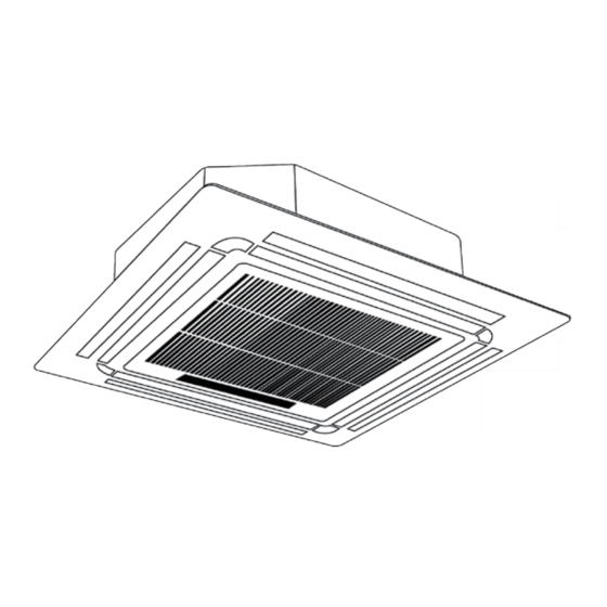
Super-Slim Four-Way Cassette
R410a Models
Indoor Unit Model
MCD-18HRFN1-QRD0
MCD-24HRFN1-QRD0
MCD-30HRFN1-QRD0
MCD-36HRFN1-QRD0
MCD-48HRFN1-QRD0
MCD-55HRFN1-QRD0
R32 Models
Indoor Unit Model
MCD-18HRFNX-QRD0
MCD-24HRFNX-QRD0
MCD-30HRFNX-QRD0
MCD-36HRFNX-QRD0
MCD-48HRFNX-QRD0
MCD-55HRFNX-QRD0
Outdoor Unit Model
MOB30U-18HFN1-QRD0
MOCA30U-24HFN1-QRD0
MOD30U-30HFN1-QRD0
MOD30U-36HFN1-QRD0
MOE30U-48HFN1-QRD0
MOE30U-55HFN1-QRD0
Outdoor Unit Model
MOB30U-18HFN8-QRD0
MOCA30U-24HFN8-QRD0
MOD30U-30HFN8-QRD0
MOD30U-36HFN8-QRD0
MOE30U-48HFN8-RRD0
MOE30U-55HFN8-RRD0
Advertisement
Table of Contents


Need help?
Do you have a question about the MCD-18HRFN1-QRD0 and is the answer not in the manual?
Questions and answers