
Related Manuals for Midea MCA3U-18HRFNX-QRD0W


Summary of Contents for Midea MCA3U-18HRFNX-QRD0W
- Page 1 SM_LC(GA)_R410A_R32_3D INV_EU_NA_1811 LIGHT COMMERCIAL INVERTER SERIES SERVICE MANUAL...
- Page 3 Table of Contents §. Safety Precautions Precautions Information servicing §. Model Reference & External Appearance Model Reference External Appearance §. Indoor Unit Indoor Unit - Compact Four-way Cassette Type Indoor Unit - A6 Duct Type Indoor Unit - Floor Ceiling Type §.
- Page 4 Table of Contents §. Troubleshooting Safety Caution General Troubleshooting Complain Record Form Information Inquiry Error Diagnosis and Troubleshooting Without Error Code Quick Maintenance by Error Code Troubleshooting by Error Code Check Procedures §. Indoor Unit Disassembly Indoor Unit - Compact Four-way Cassette Type Indoor Unit - A6 Duct Type Indoor Unit - Floor Ceiling Type §.
- Page 6 Safety Precautions Contents Precautions ......................2 Information servicing(For flammable materials) ..........3...
- Page 7 1. Precautions CAUTION To prevent personal injury, or property or unit damage, • • While unpacking be careful of sharp edges around adhere to all precautionary measures and instructions the unit as well as the edges of the fins on the con- denser and evaporator.
- Page 8 2. Information servicing(For • Prior to work taking place, the area around the equipment is to be surveyed to make sure that there are no flammable flammable materials) hazards or ignition risks. • NO SMOKING signs shall be displayed. Checks to the area Ventilated area •...
- Page 9 • that capacitors are discharged: this shall be done in shall also take into account the effects of aging or a safe manner to avoid possibility of sparking; continual vibration from sources such as compressors or fans. • that there no live electrical components and wiring are exposed while charging, recovering or purging 2.13 Detection of flammable refrigerants the system;...
- Page 10 • The refrigerant charge shall be recovered into the • Before attempting the procedure ensure that: correct recovery cylinders. The system shall be flushed • mechanical handling equipment is available, if with OFN to render the unit safe. This process may required, for handling refrigerant cylinders;...
- Page 11 • Empty recovery cylinders are evacuated and, if • The recovered refrigerant shall be returned to the possible, cooled before recovery occurs. refrigerant supplier in the correct recovery cylinder, and the relevant Waste Transfer Note arranged. Do not • The recovery equipment shall be in good working mix refrigerants in recovery units and especially not in order with a set of instructions concerning the cylinders.
- Page 12 Model Reference Contents Model Reference ....................2 External Appearance .....................3...
- Page 13 Refer to the following table to determine the specific indoor and outdoor unit model number of your purchased equipment. Universal Outdoor Unit Capacity Indoor Unit Model Power Supply Model (Btu/h) Cassette MCA3U-18HRFNX-QRD0W A6 Duct MTIU-18HWFNX-QRD0W MOB30-18HFN1-QRD0W Floor Ceiling MUEU-18HRFNX-QRD0W 1Φ, 220-240V~, 50Hz Cassette MCA3U-18HRFNX-QRD0W...
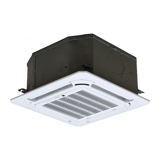
- Page 14 2. External Appearance Indoor Unit Compact Four-way Cassette A6 Duct Floor Ceiling Model Reference ...
- Page 15 Outdoor Unit Outdoor Unit Model Reference ...
-
Page 16: Table Of Contents
Indoor Unit-Compact Cassette Contents Feature........................2 Dimensional Drawings ..................4 Part names ......................5 Service Place ......................6 Accessories ......................7 Air Velocity and Temperature Distributions ............8 Capacity Tables ....................12 Noise Criterion Curves ..................18 Electrical Characteristics ..................20 Electrical Wiring Diagrams ..................20... -
Page 17: Feature
1. Feature Compact design • The body size is 570×260×570mm, it’s just smaller than the ceiling board, so it’s very easy for installation and will not damage the decoration. The panel size is 647×50×647mm. • The hooks are designed in the four corners of the body, which can save installation space. Fire-proof Controller Box •... - Page 18 Fresh Air • Fresh air intake function brings you fresh and comfortable air feeling. Wired Controller(Optional) • Compared with infrared remote controller, wired controller can be fixed on the wall and avoid mislaying. It's mainly used for commercial zone and makes air conditioner control more convenient. Louver Position Memory (Standard for ERP models) •...
-
Page 19: Dimensional Drawings
2. Dimensional Drawings IDU-Compact Cassette 4 ... -
Page 20: Part Names
3. Part names Drain pump (within indoor unit) Drain pipe Air outlet Air inlet Front grille Louver Display panel Refrigerant pipe IDU-Compact Cassette 5 ... -
Page 21: Service Place
4. Service Place IDU-Compact Cassette 6 ... -
Page 22: Accessories
5. Accessories The air conditioning system comes with the following accessories. Use all of the installation parts and accessories to in- stall the air conditioner. Improper installation may result in water leakage, electrical shock and fire, or equipment failure. Name Shape Quantity Installation paper template (some... -
Page 23: Air Velocity And Temperature Distributions
6. Air Velocity and Temperature Distributions Discharge Angle 30° Cooling airflow velocity distributions Cooling temperature distributions IDU-Compact Cassette 8 ... - Page 24 Heating airflow velocity distributions Heating temperature distributions IDU-Compact Cassette 9 ...
- Page 25 Discharge Angle 60° Cooling airflow velocity distributions Cooling temperature distributions IDU-Compact Cassette 10 ...
- Page 26 Heating airflow velocity distributions Heating temperature distributions IDU-Compact Cassette 11 ...
-
Page 27: Capacity Tables
7. Capacity Tables Cooling MCA3U-18HRFNX-QRD0W+ MOB30-18HFN8-QRD0W ID WB 16.0 18.0 19.0 22.0 INDOOR (℃) OUTDOOR AIRFLOW DB(℃) ID DB (CMH) 23.0 25.0 27.0 29.0 23.0 25.0 27.0 29.0 23.0 25.0 27.0 29.0 23.0 25.0 27.0 29.0 (℃) 5.50 5.50 5.50 5.56... - Page 28 5.62 5.62 5.62 5.68 5.90 5.90 5.90 5.90 6.06 6.06 6.06 6.06 6.43 6.43 6.43 6.43 0.68 0.75 0.98 1.00 0.55 0.63 0.70 0.76 0.49 0.56 0.63 0.70 0.36 0.42 0.48 0.55 1.11 1.11 1.11 1.11 1.10 1.10 1.10 1.10 1.10 1.10 1.10...
- Page 29 MCA3U-18HRFNX-QRD0W+ MOB30-18HFN1-QRD0W ID WB 16.0 18.0 19.0 22.0 INDOOR (℃) OUTDOOR AIRFLOW DB(℃) ID DB (CMH) 23.0 25.0 27.0 29.0 23.0 25.0 27.0 29.0 23.0 25.0 27.0 29.0 23.0 25.0 27.0 29.0 (℃) 5.50 5.50 5.50 5.56 5.78 5.90 5.90 5.90...
- Page 30 5.74 5.74 5.80 5.86 6.05 6.05 6.05 6.05 6.20 6.20 6.20 6.20 6.57 6.57 6.57 6.57 0.70 0.78 1.00 1.00 0.56 0.64 0.72 0.98 0.49 0.57 0.66 0.73 0.35 0.42 0.49 0.57 1.18 1.18 1.18 1.18 1.18 1.18 1.18 1.18 1.17 1.17 1.17...
- Page 31 Heating MCA3U-18HRFNX-QRD0W+ MOB30-18HFN8-QRD0W [SI_Unit] HEATING PERFORMANCE AT INDOOR DRY BULB TEMPERATURE TC:TOTAL CAPACITY IN KILOWATTS (KW) PI:TOTAL POWER IN KILOWATTS (KW) INDOOR OUTDOOR AIRFLOW (CMH) Indoor Conditions (DB °C ) Indoor Conditions (DB °C ) DB(°C) 16.0 20.0 22.0 24.0 16.0...
- Page 32 MCA3U-18HRFNX-QRD0W+ MOB30-18HFN1-QRD0W [SI_Unit] HEATING PERFORMANCE AT INDOOR DRY BULB TEMPERATURE TC:TOTAL CAPACITY IN KILOWATTS (KW) PI:TOTAL POWER IN KILOWATTS (KW) INDOOR OUTDOOR AIRFLOW (CMH) Indoor Conditions (DB °C ) Indoor Conditions (DB °C ) DB(°C) 16.0 20.0 22.0 24.0 16.0 20.0...
-
Page 33: Noise Criterion Curves
-Sound level will vary depending on a range of factors such as the construction -(acoustic absorption coefficient) of particular room in which the equipment is installed. -The operating conditions are assumed to be standard. Noise level dB(A) Model Sound Power dB(A) MCA3U-18HRFNX-QRD0W match with MOB30-18HFN8- 42.5 35.5 QRD0W MCA3U-18HRFNX-QRD0W match with MOB30-18HFN1- 42.5... - Page 34 MCA3U-18HRFNX-QRD0W NC-70 NC-60 NC-50 NC-40 NC-30 1000 2000 4000 8000 Band Center Frequency /Hz IDU-Compact Cassette 19 ...
-
Page 35: Electrical Characteristics
Indoor/Outdoor Connecting Strong Electric Signal 4×1.0(4×2.5 with auxiliary electric heater) Wiring (mm Weak Electric Signal 10. Electrical Wiring Diagrams IDU Model IDU Wiring Diagram Field Wiring Diagram MCA3U-18HRFNX-QRD0W 16022500004023 Abbreviation Paraphrase Yellow-Green Conductor CAP1 Indoor Fan Capacitor FAN1 Indoor Fan... - Page 36 Indoor unit wiring diagram: 16022500004023 16022500004023 NOTE: Inner Driver WIRING DIAGRAM FOR FAN MOTER Anti-cold air The wiring diagram TO WIRE SWITCH CONTROL THEN NO DC Motor NEWFAN Alarm Remote (INDOOR UNIT) POWER REQUEST. is for explanation CONTROLLER Output Control purpose only.
- Page 37 10.1 Some connectors introduce: A For remote control (ON-OFF) terminal port CN23 and short connector of JR6 1. Remove the short connector of JR6 when you use ON-OFF function; 2. When remote switch off (OPEN) ;the unit would be off; 3.
- Page 38 B For ALARM terminal port CN33 1. Provide the terminal port to connect ALARM ,but no voltage of the terminal port , the power from the ALARM system (not from the unit ) 2. Although design voltage can support higher voltage ,but we strongly ask you connect the power less than 24V, current less than 0.5A 3.
- Page 39 C. For new fresh motor terminal port CN8 1. Connect the fan motor to the port , no need care L/N of the motor ; 2. The output voltage is the power supply; 3. The fresh motor can not excess 200W or 1A , follow the smaller one ; 4.
- Page 40 10.2 Micro-Switch Introduce: A. Micro-switch SW1 is for selection of indoor fan stop temperature (TEL0) when it is in anti-cold wind action in heating mode. Range: 24 C, 15 C, 8 C, According to EEROM setting (reserved for special customizing). B.Micro-switch SW2 is for selection of indoor FAN ACTION if room temperature reaches the setponit and the compressor stops.
- Page 41 C.Micro-switch SW3 is for selection of auto-restart function. Range: Active, inactive SWITCH FOR MODE-PRIOR SETTING STATE COOL HEAT MODE HEAT COOL Factory Setting D. Micro-switch SW5 is for setting mode priority of multi connection. Range: Heat, cool. E.Micro-switch SW6 is for selection of temperature compensation in heating mode. This helps to reduce the real temperature difference between ceiling and floor so that the unit could run properly.
- Page 42 Outdoor Unit Contents Dimensional Drawings ..................2 Service Place ......................9 Capacity Correction Factor for Height Difference ..........10 Noise Criterion Curves ..................16 Refrigerant Cycle Diagrams ................18 Electrical Wiring Diagrams ..................19...
-
Page 43: Dimensional Drawings
1. Dimensional Drawings Please check the corresponding dimensional drawing according to the panel plate. ODU Model Panel Plate MOB30-18HFN8-QRD0W MOB30-18HFN1-QRD0W Outdoor Unit 2 ... - Page 44 Panel Plate B30 Outdoor Unit 3 ...
- Page 45 Panel Plate BA30 Outdoor Unit 4 ...
- Page 46 Panel Plate CA30 Outdoor Unit 5 ...
- Page 47 Panel Plate D30 Outdoor Unit 6 ...
- Page 48 Panel Plate E30 Outdoor Unit 7 ...
- Page 49 Panel Plate 590 Outdoor Unit 8 ...
-
Page 50: Service Place
2. Service Place Outdoor Unit 9 ... -
Page 51: Capacity Correction Factor For Height Difference
3. Capacity Correction Factor for Height Difference Capacity(Btu/h) Pipe Length (m) Cooling 0.973 0.948 0.936 Indoor Upper than Outdoor 0.995 0.983 0.958 0.945 Height difference 1.000 0.988 0.963 0.950 H (m) 1.000 0.988 0.963 0.950 Outdoor Upper than Indoor 0.988 0.963 0.950 Heating... - Page 52 Capacity Pipe Length (m) (Btu/h) Cooling 0.914 0.894 0.874 0.944 0.924 0.903 0.883 Indoor Upper than Outdoor 0.975 0.954 0.933 0.912 0.891 0.995 0.984 0.963 0.942 0.921 0.900 Height difference 1.000 0.989 0.968 0.947 0.926 0.905 H (m) 1.000 0.989 0.968 0.947 0.926...
- Page 53 Capacity Pipe Length (m) (Btu/h) Cooling 0.887 0.856 0.824 0.928 0.896 0.864 0.833 Indoor Upper than Outdoor 0.969 0.937 0.905 0.873 0.841 0.995 0.979 0.947 0.914 0.882 0.850 Height difference 1.000 0.984 0.951 0.919 0.886 0.854 H (m) 1.000 0.984 0.951 0.919 0.886...
- Page 54 Capacity Pipe Length (m) (Btu/h) Cooling 0.885 0.845 0.805 0.921 0.894 0.854 0.813 Indoor Upper than Outdoor 0.958 0.931 0.903 0.862 0.822 0.995 0.967 0.940 0.912 0.871 0.830 Height difference 1.000 0.972 0.945 0.917 0.876 0.834 H (m) 1.000 0.972 0.945 0.917 0.876...
- Page 55 Capacity Pipe Length (m) (Btu/h) Cooling 0.880 0.838 0.796 0.918 0.889 0.846 0.804 Indoor Upper than Outdoor 0.956 0.927 0.898 0.855 0.812 0.995 0.966 0.937 0.907 0.864 0.820 Height difference 1.000 0.971 0.941 0.912 0.868 0.824 H (m) 1.000 0.971 0.941 0.912 0.868...
- Page 56 Capacity Pipe Length (m) (Btu/h) Cooling 0.866 0.816 0.767 0.908 0.875 0.825 0.774 Indoor Upper than Outdoor 0.951 0.917 0.884 0.833 0.782 0.995 0.961 0.927 0.893 0.841 0.790 Height difference 1.000 0.966 0.931 0.897 0.846 0.794 H (m) 1.000 0.966 0.931 0.897 0.846...
-
Page 57: Noise Criterion Curves
4. Noise Criterion Curves Note: H= 0.5 × height of outdoor unit Notes: -Sound measured at 1.0m away from the center of the unit. -Data is valid at free field condition -Data is valid at nominal operation condition -Reference acoustic pressure OdB=20µPa -Sound level will vary depending on arrange off actors such as the construction (acoustic absorption coefficient) of particular room in which the equipment is installed. - Page 58 MOB30-18HFN8-QRD0W MOB30-18HFN1-QRD0W Cooling Heating Cooling Heating NC-70 NC-70 NC-60 NC-60 NC-50 NC-50 NC-40 NC-40 NC-30 NC-30 NC-20 NC-20 1000 2000 4000 8000 1000 2000 4000 8000 Band Center Frequency /Hz Band Center Frequency /Hz Outdoor Unit 17 ...
-
Page 59: Refrigerant Cycle Diagrams
5. Refrigerant Cycle Diagrams Pipe Size (Diameter:ø) Piping length (m/ft) Elevation (m/ft) mm(inch) Model No. Additional Refrigerant Liquid Rated Max. Rated Max. MOB30-18HFN8-QRD0W 12.7(1/2) 6.35(1/4) 5/16.4 30/98.4 20/65.6 12g/m (0.13oz/ft) MOB30-18HFN1-QRD0W 12.7(1/2) 6.35(1/4) 5/16.4 30/98.4 20/65.6 15g/m (0.16oz/ft) Outdoor Unit 18 ... -
Page 60: Electrical Wiring Diagrams
6. Electrical Wiring Diagrams ODU Model ODU Wiring Diagram ODU Main Printed Circuit Board MOB30-18HFN8-QRD0W 16022000031449 17122000002718 MOB30-18HFN1-QRD0W Outdoor Unit 19 ... - Page 61 Outdoor unit wiring diagram: 16022000031449 Notes: This symbol indicates the YELLOW OR BLACK element is optional,the BLUE actual shape shall be prevail. BROWN 1(L) 2(N) CN 3 CN 1 CN 2 CN 16 CN 1A INDOOR UNIT OPTIONAL POWER SUPPLY CN 60 REACTOR 4-WAY...
- Page 62 Outdoor unit printed circuit board diagram: 17122000002718...
- Page 63 Name Meaning Earth: connect to Ground Power Supply N_in: connect to N-line (208-230V AC input) L_in: connect to L-line (208-230V AC input) CN16 S: connect to indoor unit communication HEAT1 CN17 connect to compressor heater, 208-230V AC when is ON 4-WAY CN60 connect to 4 way valve, 208-230V AC when is ON.
- Page 64 Installation Contents Installation Overview Location Selection Indoor Unit Installation Outdoor Unit Installation Drainage Pipe Installation Refrigerant Pipe Installation Vacuum Drying and Leakage Checking Additional Refrigerant Charge Engineering of Insulation Engineering of Electrical Wiring Test Operation...
-
Page 65: Installation Overview
1. Installation Overview Indoor Unit Indoor Unit Install the indoor unit Install the outdoor unit Install the drainpipe Evacuate the refrigeration system Connect the wires Connect the refrigerant pipes Install the panel Perform a test run (only for cassette type) ... -
Page 66: Location Selection
2. Location selection 2.1 Unit location selection can refer to installation manual. 2.2 DO NOT install the unit in the following locations: • Where oil drilling or fracking is taking place. • Coastal areas with high salt content in the air. •... -
Page 67: Indoor Unit Installation
3. Indoor Unit Installation(Compact Cassette Type 3.1 Service space for indoor unit Suspension bolt pitch dimensions Body dimensions Decoration panel dimensions Refrigerant piping Suspension bolt (×4) Ceiling opening dimensions Hanger bracket Ceiling board 2. Drill 4 holes 5cm (2”) deep at the ceiling hook positions in the internal ceiling. - Page 68 3.3 Compact Cassette Panel Installation unit and the four sides of false ceiling are even. The 3.3.1 Remove the front grille bottom of the unit should be 24mm / 0.9in higher than ceiling board. 1. Slide the 2 grille hooks toward the middle of the Generally, L should be half the length of the suspension decoration panel.
- Page 69 3.3.6 Close the front grille, and close the two grille hooks. 3.3.3 Mount the grille Ensure that the buckles at the back of the grille be properly seated in the groove of the panel. 3.3.4 Connect the two wires of the panel to the main board of the unit.
- Page 70 3. Indoor Unit Installation(Duct) a 90° angle to the ceiling. 6. Secure the bolt using the included washers and nuts. 3.1 Service space for indoor unit 7. Install the four suspension bolts. Air outlet (30cm) 11.8 8. Mount the indoor unit with at least two people to (20cm) lift and secure it.
- Page 71 installing the indoor unit. Model(KBtu/h) Static Pressure(Pa) 0-60 0-100 24~55 0-160 Change the fan motor static pressure according to external duct static pressure. NOTE: 1.Do not put the connecting duct weight on the indoor unit. NOTE: All the figures in this manual are for demonstration purposes only.
- Page 72 3. Indoor Unit Installation(Floor MODEL(kBtu/h) Length of D (mm/inch) Length of E (mm/inch) Ceiling Type) 18~24 983/38.7 220/8.7 1200/47.2 220/8.7 3.1 Service space for indoor unit 36K~60K 1565/61.6 220/8.7 Wall-Mounted Installation 35mm/1.38in 3.3 Hang Indoor Unit 1. The installation of hanging screw bolts. •...
- Page 73 D. Refrigerant pipe connection (D.gas side) E. Refrigerant pipe connection (E. Liquid side) Drain point 8. Mount the indoor unit onto the hanging screw bolts with a block. Position the indoor unit on a flat level by using a level to Wall-Mounted Installation prevent leaks.
-
Page 74: Outdoor Unit Installation
4. Outdoor unit installation 4.3 Install Outdoor Unit Fix the outdoor unit with anchor bolts(M10) 4.1 Service space for outdoor unit >60cm / 23.6” Fix with bolts Caution Since the gravity center of the unit is not at its physical center, so please be careful when lifting it with a sling. -
Page 75: Drainage Pipe Installation
For Vertical drainage pipe (The following table is for 5. Drainage Pipe Installation reference) Install the drainage pipe as shown below and take Reference measures against condensation. Improperly installation Allowable value of inner could lead to leakage and eventually wet furniture and maximum water Remark pipe... - Page 76 ing pipe. • Each indoor unit of the system should be installed it. • The installation should be considering the conve- nience for future cleaning. • The correct installation will not cause converse water flow and the slope of the branch pipes can be adjusted freely •...
-
Page 77: Refrigerant Pipe Installation
6. Refrigerant Pipe Installation 6.1 Maximum length and drop height Ensure that the length of the refrigerant pipe, the number of bends, and the drop height between the indoor and outdoor units meets the requirements shown in the following table. For North America, Australia and Europe 3D Inverter models: Max. - Page 78 6.2 The procedure of connecting pipes • For horizontal refrigerant pipe, the distance be- tween supporters should not be exceed 1m. 1.Choose the pipe size according to the specification table. • For vertical refrigerant pipe, the distance between 2.Confirm the cross way of the pipes. supporters should not be exceed 1.5m.
-
Page 79: Vacuum Drying And Leakage Checking
7. Vacuum Drying and Leakage 4. Rain water might penetrate into pipeline during construction. Checking 7.1 Purpose of vacuum drying Procedures of special vacuum drying are as follows: • Eliminating moisture in system to prevent the phe- 1. Vacuum drying for 1 hour. nomena of ice-blockage and copper oxidation. -
Page 80: Additional Refrigerant Charge
9 . Engineering of Insulation 8. Additional Refrigerant Charge • After the vacuum drying process is carried out, the 9.1 Insulation of refrigerant pipe additional refrigerant charge process need to be 1. Operational procedure of refrigerant pipe performed. insulation • The outdoor unit is factory charged with refrigerant. -
Page 81: Engineering Of Electrical Wiring
insulation and cause easy aging of the material. Engineering of Electrical Wring 9.2 Insulation of drainage pipe 1. Highlights of electrical wiring installation 1. Operational procedure of refrigerant pipe • All field wiring construction should be finished by insulation qualified electrician. •... -
Page 82: Test Operation
4. Drainage Test 11. Test Operation a. Ensure the drainpipe flow smoothly. New buildings 1. The test operation must be carried should perform this test before finishing the ceiling. out after the entire installation has been b. Remove the test cover. Add 2000ml of water to the tank completed.
Need help?
Do you have a question about the MCA3U-18HRFNX-QRD0W and is the answer not in the manual?
Questions and answers