Table of Contents
Advertisement
Advertisement
Chapters
Table of Contents

Related Manuals for Midea MLCAC-UTSM-2010-10


Summary of Contents for Midea MLCAC-UTSM-2010-10
-
Page 1: Service Manual
MIDEA LCAC 50Hz R410A DC Inverter Service Manual 2011... - Page 3 MLCAC-UTSM-2010-10 Contents Part 1 General Information ....................1 Part 2 Indoor Units ......................6 Part 3 Outdoor Units ......................67 Part 4 Installation ......................96 Part 5 Control ........................107 ※The specifications, designs, and information in this book are subject to change without notice for product improvement.
-
Page 5: Table Of Contents
MLCAC-UTSM-2010-10 General Information Part 1 General Information 1. Model Names of Indoor/Outdoor Units ......2 2. External Appearance ............3 2.1 Indoor Units ................. 3 2.2 Outdoor Units ................3 3. Nomenclature ..............4 4. Features ................5 General Information... -
Page 6: Model Names Of Indoor/Outdoor Units
Model Names of Indoor/Outdoor Units MLCAC-UTSM-2010-10 Model Names of Indoor/Outdoor Units 1.1 Indoor Units R410A (capacity multiplied by 1000Btu/h) Type Function Four-way cassette Cooling and heating √ √ Duct Cooling and heating √ √ Ceiling & floor Cooling and heating √... -
Page 7: External Appearance
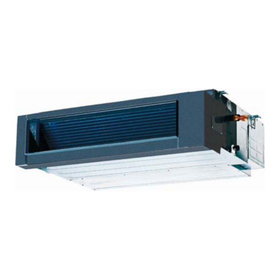
MLCAC-UTSM-2010-10 External Appearance External Appearance 2.1 Indoor Units Duct Ceiling & Floor Four-way Cassette 2.2 Outdoor Units MOUB-36HDN1-Q, MOU-48HDN1, MOUB-48HDN1-R MOUB-36HDN1-R General Information... -
Page 8: Nomenclature
Nomenclature MLCAC-UTSM-2010-10 Nomenclature 1.1 Indoor Unit M U B - 18 H R D N1 Refrigerant Type N1 R410A DC Inverter Control Mode R Remote Control Function Code C cooling Only H cooling & Heating Capacity (¡ Á 1 000Btu/h) -
Page 9: Features
MLCAC-UTSM-2010-10 Features Features 4.1 Universal outdoor unit design Indoor unit with the same capacity can match with the same outdoor unit. 4.2 High efficiency and energy saving. Thanks to the DC inverter technology and optimized piping system, the EER and COP of whole series can easily reach A-class. - Page 10 Indoor Units MLCAC-UTSM-2010-06 Part 2 Indoor Units Four-way Cassette Type ............7 Duct Type ................20 Ceiling & Floor Type ............31 Indoor Units...
- Page 11 MLCAC-UTSM-2010-10 Four-way Cassette Type Four-way Cassette Type 1. Features ................8 2. Dimensions ..............11 3. Service Space ..............12 4. Wiring Diagrams ............13 5. Air Velocity and Temperature Distributions ....14 6. Electric Characteristics ..........15 7. Sound Levels ..............15 8.
-
Page 12: Features
Features MLCAC-UTSM-2010-10 1. Features (1) Low operation noise —Streamline plate ensures quietness —Creates natural and comfortable environment (2) Efficient cooling——Equal, fast and wide range cooling (3) Excellent performance. The optimal evaporator & sufficient airflow volume guarantees the excellent capacity (4) The adoption of the most advanced 3- Dimensional Screw fan —Reduces the air resistance passing through... - Page 13 MLCAC-UTSM-2010-10 Features (8) Different color panels for choose: White、Gray、Blue、Black (9) Swing angle of louver Add one more swing motor, one motor driving two louvers. Controlling the interspace of each part, minimizing the angle loss. The swing angle of the first louver are 40~42 degrees and the second louver are 37~38 degrees.
- Page 14 Features MLCAC-UTSM-2010-10 (15) Reserve spaces for air side-outlet, it is available to connect duct pipe hence air supplying from the four sides to nearby small room.. (16) The connecting pipe and drop height is higher. Max. pipe length up to 50m (refer to ①) , and Max. drop height up to 30m(refer to ②).
-
Page 15: Dimensions
MLCAC-UTSM-2010-10 Dimensions 2. Dimensions Unit: mm MODEL(Btu/h) 36000 Ф15.9 Ф9.5 >330 48000 Ф15.9 Ф9.5 >330 Four-way Cassette Type... -
Page 16: Service Space
Service Space MLCAC-UTSM-2010-10 3. Service Space Four-way Cassette Type... -
Page 17: Wiring Diagrams
MLCAC-UTSM-2010-10 Wiring Diagrams 4. Wiring Diagrams MCC-36HRDN1、MCC-48HRDN1 Four-way Cassette Type... -
Page 18: Air Velocity And Temperature Distributions
Air Velocity and Temperature Distributions MLCAC-UTSM-2010-10 5. Air Velocity and Temperature Distributions Airflow velocity Condenser Evaporator Electronic Condenser temp. sensor expansion valve Evaporator temp. sensor High pressure switch Filter Filter Capillary Room temp. sensor Discharge temp. sensor Oil separator Ambient temp. sensor... -
Page 19: Electric Characteristics
MLCAC-UTSM-2010-10 Electric Characteristics 6. Electric Characteristics Power Indoor Unit Supply Model Voltage MCC-36HRDN1 220-240 MCC-48HRDN1 220-240 Remark: MFA: Max. Fuse Amps. (A) 7. Sound Levels Noise level dB(A) Model MCC-36HRDN1 MCC-48HRDN1 Four-way Cassette Type... -
Page 20: Accessories
Accessories MLCAC-UTSM-2010-10 8. Accessories Name Shape Quantity INSTALLATION FITTINGS Installation paper board Soundproof / insulation sheath Tubing & Fittings Connecting pipe group Out-let pipe sheath Out-let pipe clasp Drainpipe Fittings Drain joint Seal ring Remote controller & Its Frame Remote controller & Its... -
Page 21: The Specification Of Power
MLCAC-UTSM-2010-10 The Specification of Power 9. The Specification of Power Four-way Cassette Type... -
Page 22: Field Wiring
Field Wiring MLCAC-UTSM-2010-10 10. Field Wiring Wiring chart Four-way Cassette Type... - Page 23 MLCAC-UTSM-2010-10 Field Wiring Four-way Cassette Type...
-
Page 24: Duct Type
Duct Type MLCAC-UTSM-2010-10 Duct Type 1. Features ................. 21 2. Dimensions ..............22 3. Service Space ..............23 4. Wiring Diagrams ............24 5. Static Pressure .............. 25 6. Electric Characteristics ..........25 7. Sound Levels ..............26 8. Accessories ..............27 9. -
Page 25: Features
MLCAC-UTSM-2010-10 Features 1. Features ● New structure design. ● Built-in drainage pump (Optical). ● Two air intake ways: from below or rear (standard). ● Wire controller is standard. ● Three speeds indoor unit. ● Fresh air inlet hole is reserved. -
Page 26: Dimensions
Dimensions MLCAC-UTSM-2010-10 2. Dimensions Outline Air outlet o Air return Size of outline dimension mounted Capacity dimension(mm) pening size opening size plug (KBtu) MTB-36HWDN1 1140 1035 1180 MTB-48HWDN1 1200 1094 1240 Duct Type... -
Page 27: Service Space
MLCAC-UTSM-2010-10 Service Space 3. Service Space Ensure enough space required for installation and maintenance. All the indoor units reserve the hole to joint the fresh air pipe. The hole size as following: Duct Type... -
Page 28: Wiring Diagrams
Wiring Diagrams MLCAC-UTSM-2010-10 4. Wiring Diagrams MTB-36HWDN1 MTB-48HWDN1 TO WIRE DISPLAY BOARD 202 07 03903 85 CONTROLLER C ODE T ITLE FAN MOTO R PU MP M OTOR CN1 0 CN 11 WAT ER L EVEL SWI TCH H /P2... -
Page 29: Static Pressure
MLCAC-UTSM-2010-10 Static Pressure 5. Static Pressure MTB-36HWDN1 MTB-48HWDN1 Super high speed Super high speed High speed High speed Mid speed Mid speed Low speed Low speed 1100 1200 1400 1600 1800 2000 2200 2400 Air volume(m /h) 1000 1300 1600... -
Page 30: Sound Levels
Sound Levels MLCAC-UTSM-2010-10 7. Sound Levels Concealed Duct Type Discharge Suction Duct Duct 1.4m Microphone Noise level dB(A) Model MTB-36HWDN1 MTB-48HWDN1 Duct Type... -
Page 31: Accessories
MLCAC-UTSM-2010-10 Accessories 8. Accessories Name Shape Quantity Soundproof / insulation sheath Tubing & Fittings Binding tape Seal sponge Drain joint Drainpipe Fittings (for cooling & heating) Seal ring Remote controller Frame Remote controller & Its Frame Mounting screw(ST2.9 10-C-H) Alkaline dry batteries (AM4) -
Page 32: The Specification Of Power
The Specification of Power MLCAC-UTSM-2010-10 9. The Specification of Power Duct Type... -
Page 33: Field Wiring
MLCAC-UTSM-2010-10 Field Wiring 10. Field Wiring Duct Type... - Page 34 Field Wiring MLCAC-UTSM-2010-10 Air-conditioner link-circuit. Duct Type...
- Page 35 MLCAC-UTSM-2010-10 Ceiling & Floor Type Ceiling & Floor Type 1. Features ................32 2. Dimensions ..............56 3. Service Space ..............58 4. Wiring Diagrams ............. 59 5. Air Velocity and Temperature Distributions ....60 6. Electric Characteristics ..........62 7.
-
Page 36: Features
Features MLCAC-UTSM-2010-10 1. Features 1.1. New design, more modern and elegant appearance. 1.2. Convenient installation --The ceiling type can be easily installed into a corner of the ceiling even if the ceiling is very narrow --It is especially useful when installation of an air conditioner in the center of the ceiling is impossible due to a structure such as one lighting. -
Page 38: Dimensions
Dimensions MLCAC-UTSM-2010-10 2. Dimensions a. Wall mounting installation b. Ceiling installation Ceiling & Floor Type... - Page 39 MLCAC-UTSM-2010-10 Dimensions Capacity(Btu/h) MUB-36HRDN1 1280 1195 MUB-48HRDN1 1670 1070 1542 Ceiling & Floor Type...
-
Page 40: Service Space
Service Space MLCAC-UTSM-2010-10 3. Service Space Ceiling & Floor Type... -
Page 41: Wiring Diagrams
MLCAC-UTSM-2010-10 Wiring Diagrams 4. Wiring Diagrams MUB-36HRDN1、MUB-48HRDN1 Ceiling & Floor Type... -
Page 42: Air Velocity And Temperature Distributions
Air Velocity and Temperature Distributions MLCAC-UTSM-2010-10 5. Air Velocity and Temperature Distributions Discharge angle 60° (CEILING) Airflow velocity Condenser Evaporator Electronic Condenser temp. sensor expansion valve Evaporator temp. sensor High pressure switch Filter Filter Capillary Room temp. sensor Discharge temp. sensor Oil separator Ambient temp. - Page 43 MLCAC-UTSM-2010-10 Air Velocity and Temperature Distributions Discharge angle 60°(FLOOR) Airflow velocity Temperature Ceiling & Floor Type...
-
Page 44: Electric Characteristics
Electric Characteristics MLCAC-UTSM-2010-10 6. Electric Characteristics Indoor Unit Power Supply Model Voltage MUB-36HRDN1 220~240 MUB-48HRDN1 220~240 Remark: MFA: Max. Fuse Amps. (A) 7. Sound Levels Ceiling Floor Noise level dB(A) Model MUB-36HRDN1 MUB-48HRDN1 Ceiling & Floor Type... -
Page 45: Accessories
MLCAC-UTSM-2010-10 Accessories 8. Accessories Name Shape Quantity 1.Hook Installation fittings 2.Hanging arm 3. Remote controller Remote controller & Its 4. Remote controller holder holder 5. Mounting screw (ST2.9×10-C-H) 6. Alkaline dry batteries (AM4) 7. Owner's manual Others 8. Installation manual 9. -
Page 46: The Specification Of Power
The Specification of Power MLCAC-UTSM-2010-10 9. The Specification of Power Ceiling & Floor Type... -
Page 47: Field Wiring
MLCAC-UTSM-2010-10 Field Wiring 10. Field Wiring Ceiling & Floor Type... - Page 48 Field Wiring MLCAC-UTSM-2010-10 Ceiling & Floor Type...
- Page 49 MLCAC-UTSM-2010-10 Outdoor Unit Part 3 Outdoor Units 1. Dimensions ..............68 2. Service Space ..............69 3. Piping Diagrams.............. 70 4. Wiring Diagrams ............. 71 5. Electric Characteristics ..........73 6. Operation Limits ............. 74 7. Sound Levels ..............75 8.
- Page 50 Dimensions MLCAC-UTSM-2010-10 1. Dimensions Unit: mm MODEL MOUB-36HDN1-Q 1245 MOUB-36HDN1-R MOU-48HDN1 1245 MOUB-48HDN1-R 1245 Outdoor Units...
-
Page 51: Service Space
MLCAC-UTSM-2010-10 Service Space 2. Service Space Outdoor Units... -
Page 52: Piping Diagrams
Piping Diagrams MLCAC-UTSM-2010-10 3. Piping Diagrams MOUB-36HDN1-Q、MOU-48HDN1、MOUB-36HDN1-R、MOUB-48HDN1-R Condenser Evaporator Electronic Condenser temp. sensor expansion valve Evaporator temp. sensor High pressure switch Filter Filter Capillary Room temp. sensor Discharge temp. sensor Oil separator Ambient temp. sensor 4-way valve Filter Oil return... -
Page 53: Wiring Diagrams
MLCAC-UTSM-2010-10 Wiring Diagrams 4. Wiring Diagrams MOUB-36HDN1-Q MOU-48HDN1 MOUB-36HDN1-R Outdoor Units... - Page 54 Wiring Diagrams MLCAC-UTSM-2010-10 MOUB-48HDN1-R Outdoor Units...
-
Page 55: Electric Characteristics
MLCAC-UTSM-2010-10 Electric Characteristics 5. Electric Characteristics Outdoor Unit Power Supply Model Voltage Min. Max. MOUB-36HDN1-Q 220-240 MOUB-36HDN1-R 380-415 MOU-48HDN1 220-240 MOUB-48HDN1-R 380-415 Remark: MFA: Max. Fuse Amps. (A) Outdoor Units... -
Page 56: Operation Limits
Operation Limits MLCAC-UTSM-2010-10 6. Operation Limits Heating Indoor temperature( ℃ DB) Outdoor Units... -
Page 57: Sound Levels
MLCAC-UTSM-2010-10 Sound Levels 7. Sound Levels Noise level dB(A) Model MOUB-36HDN1-Q 57/52 MOUB-36HDN1-R 55/50 MOU-48HDN1 59/54 MOUB-48HDN1-R 59/54 Outdoor Units... -
Page 58: Troubleshooting
Troubleshooting MLCAC-UTSM-2010-10 8. Troubleshooting 8.1 Indoor unit malfunction 8.1.1 Display board Ceiling & Floor Normal 4-way cassette Duct Outdoor Units... - Page 59 MLCAC-UTSM-2010-10 Troubleshooting 8.1.2 Troubleshooting For Normal 4-way cassette For ceiling & floor Outdoor Units...
- Page 60 Troubleshooting MLCAC-UTSM-2010-10 For Duct type Outdoor Units...
- Page 61 MLCAC-UTSM-2010-10 Troubleshooting 1. Operation lamp flashes Operation lamp flashes at 5Hz Judge 1: Indoor temp. sensor is abnormal Check whether the resistance of the evaporator temp. sensor is Replace evaporator temp. sensor correct according to Annex 1 Judge 2: Room temp. sensor is abnormal Check whether the resistance of the room temp.
- Page 62 Troubleshooting MLCAC-UTSM-2010-10 2. Timer lamp flashes Timer lamp flashes at 5Hz Judge: Indoor/outdoor unit communication is abnormal Refer to the outdoor unit LED display E2 malfunction in the following part 3. Alarm lamp slow-flash Indoor alarm lamps flash at 1Hz Condenser temp.
- Page 63 MLCAC-UTSM-2010-10 Troubleshooting 3. Alarm lamp quick-flash Alarm lamp flashes at 5Hz Judge: Water level switch is abnormal. Replace water pump Check whether the water pump can work normally Select the cooling mode to make water pump work for a few minutes, then check...
- Page 64 Troubleshooting MLCAC-UTSM-2010-10 9.2 Outdoor unit malfunction Display Malfunction or Protection EEPROM malfunction Communication malfunction between indoor IC and outdoor IC Communication malfunction in outdoor IC and DSP Malfunction of outdoor temperature sensor Voltage protection of compressor PFC module protection (Only for 30K, 36K & 48K with 1 phase)
- Page 65 MLCAC-UTSM-2010-10 Troubleshooting 2. E2 malfunction E2 display Communication malfunction between indoor IC and outdoor IC Turn on the indoor unit power Judge 1: Check whether the indoor unit power is on Judge 2: Check whether the signal wiring is shield cable or whether...
- Page 66 Troubleshooting MLCAC-UTSM-2010-10 3. E3 malfunction (For 18K & 24K & 30K) E3 display Communication malfunction in outdoor IC and DSP Check whether the indicator lights LED1 on the main board is flashing Replace the outdoor main board Insert the connecting wiring well over...
- Page 67 MLCAC-UTSM-2010-10 Troubleshooting 4. E3 malfunction (For 36K & 48K & 60K) E3 display Communication malfunction in outdoor IC and DSP Check whether the indicator lights LED1 or LED2 on the main control board are flashing Replace PCB Install the IC-U3 chip of the PCB over again, check whether the system...
- Page 68 Troubleshooting MLCAC-UTSM-2010-10 5. E4 malfunction E4 display Judge 1: Outdoor condenser temp. sensor (T3) is malfunction Connect the wiring well Check whether the wiring of the condenser temp. sensor is broken off Check whether the resistance of condenser temp. sensor is wrong refer to the Annex 1 Replace condenser temp.
- Page 69 MLCAC-UTSM-2010-10 Troubleshooting 6. E5 malfunction E5 display Voltage protection of compressor Check the voltage of outdoor unit power supply, whether the voltage Check the power supply between L(1) and N is about 172-265V Replace the power board, then check whether the system can run normally...
- Page 70 Troubleshooting MLCAC-UTSM-2010-10 8. P1 malfunction P1 display High pressure protection Judge 1: Whether the wiring between the high pressure switch and main Connect it well control board is connected well or correctly Judge 2: Whether the high pressure switch is broken...
- Page 71 MLCAC-UTSM-2010-10 Troubleshooting 9. P2 malfunction P2 display Low pressure protection Judge 1: The wiring between the low pressure switch and main control board is connected well or correctly Connect it well Judge 2: Whether the low pressure switch is broken...
- Page 72 Troubleshooting MLCAC-UTSM-2010-10 10. P3 malfunction P3 display Current protection of compressor Judge 1: Check whether the input current of the power supply wire is more than 20A (For 36K & 48K with 1 phase, it is 30A) Check whether the refrigerant system is ok...
- Page 73 MLCAC-UTSM-2010-10 Troubleshooting 11. P4 malfunction When compressor discharge temperature is higher than 115°C, the unit will stop, and unit runs again when compressor discharge temperature is lower than 90°C. P4 display Discharge temperature protection of compressor Check whether the compressor discharge temp. is more than 115°C ? Check whether the wiring connection is right between compressor discharge temp.
- Page 74 Troubleshooting MLCAC-UTSM-2010-10 12. P5 malfunction When condenser high temp. is more than 65°C, the unit will stop, and unit runs again when outdoor pipe temp. less than 52°C. P5 display High temperature protection of condenser Check whether the condenser temperature is more than 65°C Check whether the resistance of condenser temp.
- Page 75 MLCAC-UTSM-2010-10 Troubleshooting 13. P6 malfunction (For single phase units) P6 display Module protection Check whether the voltage range of P-N on IPM module is normal? DC277-356V for Regulate it to correct, 18K/24K/30KBtu/h; DC277-410V for then check whether the 36K/48KBtu/h Check whether the input power supply...
- Page 76 Troubleshooting MLCAC-UTSM-2010-10 14. P6 malfunction (For three phases units) P6 display Module protection Regulate it to correct, then check whether the Check whether the voltage range of P-N on Check whether the input power supply system can work IPM module is normal? DC 350-650V...
- Page 77 MLCAC-UTSM-2010-10 Troubleshooting Appendix Indoor Temp. and Pipe Temp. Sensor Resistance Value Table (℃--K) ℃ K Ohm ℃ K Ohm ℃ K Ohm ℃ K Ohm 115.266 12.6431 2.35774 0.62973 108.146 12.0561 2.27249 0.61148 101.517 11.5000 2.19073 0.59386 96.3423 10.9731 2.11241 0.57683...
- Page 78 Installation MLCAC-UTSM-2010-10 Part 4 Installation 1.Precaution on Installation ........... 97 2.Vacuum Dry and Leakage Checking ......... 98 3.Additional Refrigerant Charge .........100 4.Water Drainage ..............101 5.Insulation Work ..............104 6.Wiring ................105 7.Test Operation ..............106 Installation...
-
Page 79: Precaution On Installation
MLCAC-UTSM-2010-10 Precaution on Installation 1. Precaution on Installation 1). Measure the necessary length of the connecting pipe, and make it by the following way. Connect the indoor unit at first, then the outdoor unit. Bend the tubing in proper way. Do not harm them. -
Page 80: Vacuum Dry And Leakage Checking
Vacuum Dry and Leakage Checking MLCAC-UTSM-2010-10 2. Vacuum Dry and Leakage Checking Vacuum Dry: use vacuum pump to change the moisture (liquid) into steam (gas) in the pipe and discharge it out of the pipe to make the pipe dry. Under one atmospheric pressure, the boiling point of water(steam temperature) is 100 . Use vacuum pump to make the pressure in the pipe near vacuum state, the boiling point of water falls relatively. - Page 81 MLCAC-UTSM-2010-10 Vacuum Dry and Leakage Checking . Special vacuum dry procedure This vacuum dry method is used in the following conditions: There’s moisture when flushing the refrigerant pipe. Rainwater may enter into the pipe. Vacuum dry for the first time ······ 2h pumping ...
-
Page 82: Part 3 Outdoor Units
Additional Refrigerant Charge MLCAC-UTSM-2010-10 3. Additional Refrigerant Charge Caution Refrigerant cannot be charged until field wiring has been completed. b) Refrigerant may only be charged after performing the leak test and the vacuum pumping. When charging a system, care shall be taken that its maximum permissible charge is never exceeded, in view of the danger of liquid hammer. -
Page 83: Water Drainage
MLCAC-UTSM-2010-10 Water Drainage 4. Water Drainage 4.1 Gradient and Supporting 1). Keep the drainpipe sloping downwards at a gradient of at least 1/50. Keep the drainpipe as short as possible and eliminate the air bubble. 2). The horizontal drainpipe should be short. When the pipe is too long, a prop stand must be installed to keep the gradient of 1/50 and prevent bending. -
Page 84: Drainage Test
Water Drainage MLCAC-UTSM-2010-10 For Four-way cassette 4.4 Convergent drainage 1). The number of indoor units should be as small as possible to prevent the traverse main pipe overlong. 2). Indoor unit with drain pump and indoor unit without drain pump should be in different drainage system. - Page 85 MLCAC-UTSM-2010-10 Water Drainage Stop the air conditioner running, turn off the power, and put back the cover. Stop the air conditioner. After 3 minutes, check if it has abnormity. If the collocation of drainpipes is illogical, the water will flow back overfull, which will cause the alarm lamp flashes, even overflow from the water receipt plate.
-
Page 86: Part
Insulation Work MLCAC-UTSM-2010-10 5. Insulation Work 5.1 Insulation material and thickness 1). Insulation material Insulation material should adopt the material which is able to endure the pipe’s temperature: no less than 70 in the high-pressure side, no less than 120 in the low-pressure side(For the cooling type machine, no requirements at the low-pressure side.) -
Page 87: Drainage Pipe Insulation
MLCAC-UTSM-2010-10 Insulation Work For construction convenience, before laying pipes, use insulation material to insulate the pipes to be deal with, at the same time, at two ends of the pipe, remain some length not to be insulated, in order to be welded and check the leakage after laying the pipes. -
Page 88: Test Operation
Test Operation MLCAC-UTSM-2010-10 7. Test Operation (1) The test operation must be carried out after the entire installation has been completed. (2) Please confirm the following points before the test operation. The indoor unit and outdoor unit are installed properly. - Page 89 MLCAC-UTSM-2010-10 Control Part 5 Control 1. Controller ................ 108 Control...
- Page 90 Controller MLCAC-UTSM-2010-10 1. Controller 1.1 R05/BGE The R05/BGE wireless remote controller is for Four-way cassette type and the Ceiling& floor type. AUTO TE MP C O O L Mo de s etting Fan s peed se tti n g H E AT...
- Page 91 MLCAC-UTSM-2010-10 Controller Buttons and functions 1. MODE: Once pressing, running mode will be selected in the following sequence: AUTO COOL HEAT FAN NOTE: No heating mode for cool only type unit. 2. FAN SPEED: Fan speed will be selected in following sequence once pressing this button:...
- Page 92 Controller MLCAC-UTSM-2010-10 1.2 KJR-10B NAME AND FUNCTION OF LCD ON THE WIRE CONTROLLER Mode select button (MODE): Press MODE button to select “COOL”, “DRY” , "HEAT", or "FAN ONLY" mode.(HEAT is invalid for COOL ONLY wire controller.) AUTO→ COOLING →DEHUMIDIFY →HEATING→ FAN Fan speed button (FAN SPEED) Press FAN SPEED to select fan speed from "AUTO", "LOW","...
- Page 93 MLCAC-UTSM-2010-10 Controller Press ECONOMICAL to display economical operation, if press ECONOMICAL again then the display disappears Lock display Press LOCK to display the icon of LOCK. Press the button again then the icon of LOCK disappears. In the mode of LOCK, all the buttons are invalid except for LOCK button.
- Page 94 Controller MLCAC-UTSM-2010-10 Push the button to set TIMER ON, each time you push the button the time moves forward by o.5 hours. When the set time is over 10 hours, each time you push the button the time moves forward by 1 hour. If want to cancel the TIMER ON, then adjust the time of TIMER ON as 0.0...
- Page 95 MLCAC-UTSM-2010-10 Controller Installation Installation Notice: When the air conditioner needs the constant frequency wire Controller, be sure adding a Wire Joint with 5 terminal named A, B, C, D, E in indoor unit, and fixing a infrared emitter whose anode and cathode connecting with A and B near the receiver in the Indoor Unit Switch Board, then connecting the terminal +5v, GND, Run in the Switch Board to C,D,E respectively.
Need help?
Do you have a question about the MLCAC-UTSM-2010-10 and is the answer not in the manual?
Questions and answers