Table of Contents
Advertisement
Advertisement
Chapters
Table of Contents

Related Manuals for Midea MOU-18HN1-Q


Summary of Contents for Midea MOU-18HN1-Q
- Page 1 R410A ON/OFF SERIES Service Manual 2013 LEUS-B-1306 Contents...
-
Page 3: Part 5 Electrical Control System
Content Part 1 General Information ..............1 Part 2 Indoor Units ................6 Part 3 Outdoor Units ................63 Part 4 Installation ................78 Part 5 Electrical Control System .............104 ※The specifications, designs, and information in this book are subject to change without notice for product improvement. -
Page 5: Table Of Contents
General Information Part 1 General Information 1. Model Lists ........................2 2. External Appearance ....................... 3 2.1 Indoor Units ....................... 3 2.2 Outdoor Units ......................3 3. Nomenclature ........................4 4. Features ..........................5 General Information... -
Page 6: Model Lists
Cooling and heating ● High static pressure duct Cooling and heating 1.2 Outdoor Units Universal Outdoor unit Model Compressor type Compressor Brand Matched indoor units Heat Pump MHF-18HWN1-Q MOU-18HN1-Q ROTARY CMCC MCD-18HRN1-Q MHF-24HWN1-Q MOU-24HN1-Q ROTARY CMCC MCD-24HRN1-Q MHG-24HWN1-Q MOU-30HN1-Q ROTARY... -
Page 7: External Appearance
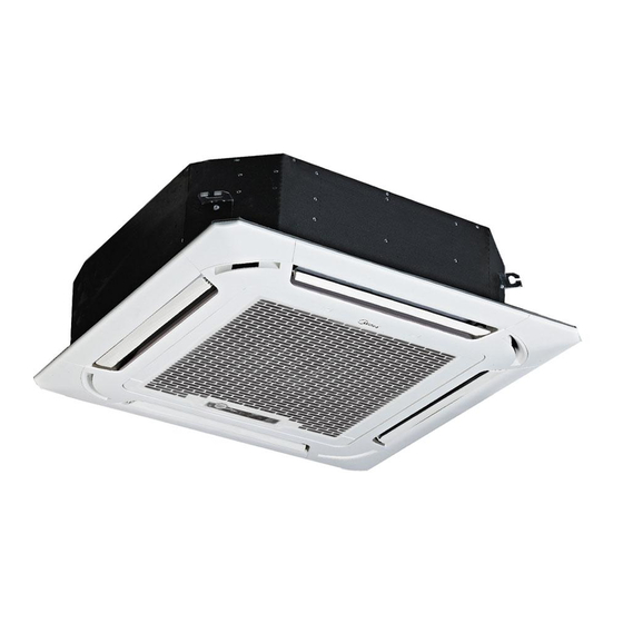
External Appearance 2. External Appearance 2.1 Indoor Units A5 High static pressure duct Ceiling & floor type Super-slim 4-way Cassette High static pressure duct 2.2 Outdoor Units Single fan outdoor unit Double fan outdoor unit General Information... -
Page 8: Nomenclature
V AHU Type T Duct Type F Console Type U Ceiling & Floor Type H High Static Pressure Duct Type Midea 3.2 Outdoor Unit M O U T- 36 H D N1- R RC4 Energy Efficiency Code Power Supply Q 220~240V,1N, 50HZ... -
Page 9: Features
Features 4. Features 4.1 High quality coils: The coil is constructed of advanced inner grooved copper tube and aluminum fins. 4.2 Anti-rust, 500 hours salt spray test. 4.3 Low operation sound level: Well-known stable and quiet running fan motor. 4.4 Well-known compressor. 4.5 Compact design: Smaller dimension and larger stuffing capacity. -
Page 10: Part 2 Indoor Units
Indoor Units Part 2 Indoor Units A5 High Static Pressure Duct Type ........7 Ceiling & Floor Type ............25 Super-slim Cassette Type ..........35 High Static Pressure Duct Type ......... 52 Indoor Units... - Page 11 A5 High Static Pressure Duct Type A5 High Static Pressure Duct Type 1. Features ...................... 8 2. Dimensions ....................11 3. Service Space ................... 12 4. Wiring Diagrams ..................13 5. Static Pressure ..................18 6. Electric Characteristics ................19 7.
-
Page 12: Features
Features 1. Features 1.1 Installation accessories: (Optional) Front Board, Canvas Air Passage, Filter, Panel, for easy installation Front Board Canvas Air Passage Filter Panel 1.2 Easy Installation: Two air inlet styles (Bottom side or Rear side) Air inlet from rear is standard for all capacity; air inlet from bottom is optional. ... - Page 13 Features Motor Blower Housing Ventilated Panel 1.4 Reserved remote on-off and central control ports Reserved remote on-off ports and central control ports, can connect the cable of an on-off controller or a central controller to realize remote on-off control function or group control function. Remote on-off ports Central control ports 1.5 Built-in drain pump (Optional):...
- Page 14 Features 1.6 Built-in display board The standard indoor unit can be controlled by wired controller. There is a display board with a receiver in the E-box. Move out the display, and fix it in other place, even in the distance of 10m. The unit will realized remoter control. ...
-
Page 15: Dimensions
Dimensions 2. Dimensions Outline Air outlet Air return Size of outline dimension Capacity dimension(mm) opening size opening size mounted plug (KBtu) 30/36 1140 1035 1180 48/60 1200 1094 1240 Duct Type... -
Page 16: Service Space
Service Space 3. Service Space Ensure enough space required for installation and maintenance. Duct Type... -
Page 17: Wiring Diagrams
Wiring Diagrams 4. Wiring Diagrams MHF-18HWN1-Q Duct Type... - Page 18 Wiring Diagrams MHF-24HWN1-Q Duct Type...
- Page 19 Wiring Diagrams MHF-30HWN1-Q、MHF-36HWN1-Q Duct Type...
- Page 20 Wiring Diagrams MHF-30HWN1-R、MHF-36HWN1-R、MHF-48HWN1-R、MHF-60HWN1-R Duct Type...
- Page 21 Wiring Diagrams Duct Type...
-
Page 22: Static Pressure
Static Pressure 5. Static Pressure 18,000 Btu/h 24,000 Btu/h Super high speed Super high speed High speed High speed Mid speed Mid speed Low speed Low speed 1000 1100 1200 1300 1400 1500 1600 1000 1100 1200 1300 1400 1500 Air volume(m /h) Air volume(m /h) 30,000 Btu/h... -
Page 23: Electric Characteristics
Electric Characteristics lectric Characteristics Indoor Units Power Supply Model Voltage Min. Max. MHF-18HWN1-Q 220-240V 198V 254V MHF-24HWN1-Q 220-240V 198V 254V MHF-30HWN1-Q 220-240V 198V 254V MHF-30HWN1-R 380-420V 342V 440V MHF-36HWN1-Q 220-240V 198V 254V MHF-36HWN1-R 380-420V 342V 440V MHF-48HWN1-R 380-420V 342V 440V MHF-60HWN1-R 380-420V 342V... -
Page 24: Sound Levels
Sound Levels 7. Sound Levels Concealed Duct Type Discharge Suction Duct Duct 1.4m Microphone Noise level dB(A) Model MHF-18HWN1-Q MHF-24HWN1-Q MHF-30HWN1-Q MHF-30HWN1-R MHF-36HWN1-Q MHF-36HWN1-R MHF-48HWN1-R MHF-60HWN1-R Duct Type... -
Page 25: Accessories
Accessories 8. Accessories Name Shape Quantity Soundproof/insulation sheath Tubing & Fittings Binding tape Seal sponge Drain joint Drainpipe Fittings Seal ring Wire controller Wire controller Owner's manual others Installation manual Duct Type... -
Page 26: The Specification Of Power
The Specification of Power 9. The Specification of Power 30000-36000 30000-60000 Model Btu/h Btu/h 18000 24000 Btu/h Btu/h Phase 1-Phase 1-Phase 1-Phase 3-Phase Power Frequency and Volt 220-240V 50Hz 220-240V 50Hz 220-240V 50Hz 380-415V 50Hz Circuit Breaker/Fuse(A) 20/16 40/25 50/30 25/20 Indoor unit power wiring(mm²) 3×2.5... -
Page 27: Field Wiring
Field Wiring 10. Field Wiring MHF-18HWN1-Q Duct Type... - Page 28 Field Wiring MHF-24HWN1-Q、MHF-30HWN1-Q、MHF-36HWN1-Q MHF-30HWN1-R、MHF-36HWN1-R、MHF-48HWN1-R、MHF-60HWN1-R Duct Type...
-
Page 29: Ceiling & Floor Type
Ceiling & Floor Type Ceiling & Floor Type 1. Features ................26 2. Dimensions ..............27 3. Service Space ..............28 4. Wiring Diagrams ............. 29 5. Electric Characteristics ..........31 6. Sound Levels ..............31 ... -
Page 30: Features
Features Features 1.1. New design, more modern and elegant appearance. 1.2. Convenient installation --The ceiling type can be easily installed into a corner of the ceiling even if the ceiling is very narrow --It is especially useful when installation of an air conditioner in the center of the ceiling is impossible due to a structure such as one lighting. -
Page 31: Dimensions
Dimensions Dimensions Capacity (Btu/h) 1285 1200 48K, 60K 1650 1565 Ceiling & Floor Type... -
Page 32: Service Space
Service Space Service Space Ceiling & Floor Type... -
Page 33: Wiring Diagrams
Wiring Diagrams Wiring Diagrams MUE-36HRN1-Q Ceiling & Floor Type... - Page 34 Wiring Diagrams MUE-36HRN1-R、MUE-48HRN1-R、MUE-60HRN1-R Ceiling & Floor Type...
-
Page 35: Electric Characteristics
Electric Characteristics Electric Characteristics Indoor Units Power Supply Model Voltage Min. Max. MUE-36HRN1-Q 220-240V 198V 242V MUE-36HRN1-R 380-420V 342V 440V MUE-48HRN1-R 380-420V 342V 440V MUE-60HRN1-R 380-420V 342V 440V Remark: MFA: Max. Fuse Amps. (A) Sound Levels Microphone 1.5m Air outlet side Microphone Ceiling Floor... -
Page 36: Accessories
Accessories Accessories 1. Remote controller Remote controller & Its 2. Remote controller holder holder 3. Mounting screw (ST2.9×10-C-H) 4. Alkaline dry batteries (AM4) 5. Owner's manual Others 6. Installation manual 7. Remote controller manual The Specification of Power Model 36000 Btu/h 30000-60000 Btu/h Phase 1-Phase... -
Page 37: Field Wiring
Field Wiring Field Wiring MUE-36HRN1-Q Ceiling & Floor Type... - Page 38 Field Wiring MUE-36HRN1-R、MUE-48HRN1-R、MUE-60HRN1-R Ceiling & Floor Type...
-
Page 39: Super-Slim Cassette Type
Super-slim Cassette Type Super-slim Cassette Type Features ..............36 Dimensions ..............40 Service Space ............. 41 Wiring Diagrams ............42 Electric Characteristics ..........46 Sound Levels .............. 47 Accessories .............. -
Page 40: Features
Features 1. Features Overview Compact design, super slim body size, less space requiring in installation Each louver can be separately controlled, more comfort air blowing is possible. Auto-lifting panel design, more convenient to clean and maintain the filter. (optional) Old Cassette New slim cassette Volume change... - Page 41 Features New air-intake Optional ionizer generator Ionizer generator is optional to get refreshing air to your room. Ionizer can be switched on or off by remote controller. When pressing the Clean Air button on the remote controller, Ionizer will work and the indicator light on display board will shine.
- Page 42 Features External air duct design Reserve external air duct, more flexible for the air supply. Built-in draining pump Due to the improvement of structure, more convenient to repair or replace the draining pump. Draining Pump Built-in draining pump to make sure condensed water drain out reliably. Super-slim Cassette Type...
- Page 43 Features Terminals for alarm lamp and long-distance on-off controller connection are standard Reserve terminals for the connection of alarm lamp and long-distance on-off controller, more human control. Alarm lamp Long-distance on-off controller Optional touch screen wired controller Touch screen wired controller is optional, with error code indication function. Better man-machine conversation interface.
-
Page 44: Dimensions
Dimensions 2. Dimensions Model 18-30 >235 36-48 >275 >317 Super-slim Cassette Type... -
Page 45: Service Space
Service Space 3. Service Space >1000mm >1000mm Super-slim Cassette Type... -
Page 46: Wiring Diagrams
Wiring Diagrams 4. Wiring Diagrams MCD-18HRN1-Q Super-slim Cassette Type... - Page 47 Wiring Diagrams MCD-24HDN1-Q Super-slim Cassette Type...
- Page 48 Wiring Diagrams MCD-36HDN1-R Super-slim Cassette Type...
- Page 49 Wiring Diagrams MCD-48HDN1-R MCD-60HDN1-R Super-slim Cassette Type...
-
Page 50: Electric Characteristics
Electric Characteristics 5. Electric Characteristics Power Indoor Unit Supply Model Voltage 220-240V 198V 254V MCD-18HRN1-Q 220-240V 198V 254V MCD-24HRN1-Q 380-420V 342V 440V MCD-36HRN1-R 380-420V 342V 440V MCD-48HRN1-R 380-420V 342V 440V MCD-60HRN1-R Notes: MFA: Max. Fuse Amps. (A) Super-slim Cassette Type... -
Page 51: Sound Levels
Sound Levels 6. Sound Levels 1.4m Microphone Noise level dB(A) Model MCD-18HRDN1-Q MCD-24HRDN1-Q MCD-36HRDN1-R MCD-48HRDN1-R MCD-60HRDN1-R Super-slim Cassette Type... -
Page 52: Accessories
Accessories 7. Accessories Name Shape Quantity Installation paper board INSTALLATION FITTINGS Bolt M5 Tubing & Fittings Soundproof / insulation sheath Out-let pipe Out-let pipe sheath Drainpipe Fittings Out-let pipe clasp Remote controller & Its Frame Remote controller holder Remote controller & Its Frame Mounting screw(ST2.9×10-C-H) Remote controller manual... -
Page 53: The Specification Of Power
The Specification of Power 8. The Specification of Power Model 18000 Btu/h 24000 Btu/h 36000-60000 Btu/h Phase 1-Phase 1-Phase 3-Phase Power Frequency and Volt 220-240V 50Hz 220-240V 50Hz 380-415V 50Hz Circuit Breaker/Fuse(A) 20/16 40/25 25/20 Indoor unit power wiring(mm²) 3×2.5 3×2.5 5×2.5 Ground wiring... -
Page 54: Field Wiring
Field Wiring 9. Field Wiring MCD-18HRN1-Q Super-slim Cassette Type... - Page 55 Field Wiring MCD-24HRN1-Q MCD-36HRN1-R MCD-48HRN1-R MCD-60HRN1-R Super-slim Cassette Type...
-
Page 56: High Static Pressure Duct Type
High Static Pressure Duct Type High Static Pressure Duct Type 1. Features ................53 2. Dimensions ..............54 3. Service Space ..............55 4. Wiring Diagrams ............. 56 5. Static Pressure ..............57 1. Electric Characteristics ..........58 ... -
Page 57: Features
Features Features 1.1 High static pressure design Max static pressure of indoor unit is 200Pa. The longest distance of air supply is 14m, the max height of air supply is 6.5m. Specially recommended for spacious and large rooms like large stores and factories. High static pressure design enables long duct. -
Page 58: Dimensions
Dimensions 2. Dimensions 24K-48K Size of Outline dimension Air outlet opening size Air inlet opening size Capacity mounted lug (KBtu) 1110 1146 1054 1075 (Unit: mm) High Static Pressure Duct Type... -
Page 59: Service Space
Service Space 3. Service Space Ensure enough space required for installation and maintenance. 500mm or more 600mm or more Indoor unit Maintenance and repair space 600mmx600mm High Static Pressure Duct Type... -
Page 60: Wiring Diagrams
Wiring Diagrams 4. Wiring Diagrams MHG-24HWN1-Q High Static Pressure Duct Type... -
Page 61: Static Pressure
Static Pressure 5. Static Pressure 24,000Btu/h High Static Pressure Duct Type... -
Page 62: Electric Characteristics
Electric Characteristics 6. Electric Characteristics Indoor Unit Power Supply Model Voltage Min. Max. 220-240 MHG-24HWN1-Q Notes: MFA: Max. Fuse Amps. (A) High Static Pressure Duct Type... -
Page 63: Sound Levels
Sound Levels 7. Sound Levels Concealed Duct Type Discharge Suction Duct Duct 1.5m Microphone Noise level dB(A) Model MHG-24HWN1-Q High Static Pressure Duct Type... -
Page 64: Accessories
Accessories Accessories Name Shape Quantity Tubing & Fittings Soundproof / insulation sheath Drain joint Drainpipe Fittings (for cooling & heating) Seal ring Wired controller Wired controller & Its Frame Owner , s manual of wired controller Wired controller installation manual Owner ,... -
Page 65: The Specification Of Power
The Specification of Power 9. The Specification of Power Model 24000 Btu/h Phase 1-Phase Power Frequency and Volt 220-240V 50Hz Circuit Breaker/Fuse(A) 40/25 Indoor unit power wiring(mm²) 3×2.5 Ground wiring Outdoor unit power wiring 3×2.5 Indoor/out-door connecting wiring(mm²) Strong electric signal 3×1.0 Weak electric signal 2×0.2... -
Page 66: Field Wiring
Field Wiring 10. Field Wiring MHG-24HWN1-Q High Static Pressure Duct Type... -
Page 67: Part 3 Outdoor Units
Outdoor Units Part 3 Outdoor Units 1. Dimensions ..............64 2. Service Space ..............66 3. Piping Diagrams .............. 67 4. Wiring Diagrams .............. 69 5. Electric Characteristics ........... 75 6. Operation Limits .............. 76 7. Sound Levels ..............77 Outdoor Units... -
Page 68: Dimensions
Dimensions 1. Dimensions Unit:mm Model MOU-18HN1-Q MOU-24HN1-Q MOU-30HN1-Q MOU-30HN1-R MOU-36HN1-Q MOU-36HN1-R Outdoor Units... - Page 69 Dimensions Unit:mm Model MOU-48HN1-R 1170 MOUA-60HN1-R 1170 Outdoor Units...
-
Page 70: Service Space
Service Space 2. Service Space (Wall or obstacle) More than 30cm Air inlet More than 60cm More than 30cm Maintain channel Air inlet More than 60cm Air outlet More than 200cm Outdoor Units... -
Page 71: Piping Diagrams
Piping Diagrams 3. Piping Diagrams MOU-18HN1-Q、MOU-24HN1-Q、MOU-30HN1-Q、MOU-30HN1-R INDOOR OUTDOOR CHECK VALVE LIQUID SIDE (Heating Model only) 2-WAY VALVE T3 Condenser temp. sensor CAPILIARY TUBE HEAT HEAT EXCHANGE EXCHANGE (EVAPORATOR) (CONDENSER) T1 Room temp. T4 Ambient sensor temp. sensor T2 Evaporator temp. sensor... - Page 72 Piping Diagrams MOU-48HN1-R、MOUA-60HN1-R INDOOR OUTDOOR CHECK VALVE LIQUID SIDE (Heating Model only) 2-WAY VALVE T3 Condenser temp. sensor CAPILIARY TUBE HEAT EXCHANGE HEAT (EVAPORATOR) T4 Ambient T1 Room temp. EXCHANGE temp. sensor sensor (CONDENSER) T2 Evaporator temp. sensor GAS SIDE 4-WAY VALVE High pressure switch 3-WAY VALVE...
-
Page 73: Wiring Diagrams
Wiring Diagrams 4. Wiring Diagrams MOU-18HN1-Q Outdoor Units... - Page 74 Wiring Diagrams MOU-24HN1-Q MOU-30HN1-Q Outdoor Units...
- Page 75 Wiring Diagrams MOU-30HN1-R MOU-36HN1-Q Outdoor Units...
- Page 76 Wiring Diagrams MOU-36HN1-R Outdoor Units...
- Page 77 Wiring Diagrams MOU-48HN1-R Outdoor Units...
- Page 78 Wiring Diagrams MOUA-60HN1-R Outdoor Units...
-
Page 79: Electric Characteristics
Electric Characteristics 5. Electric Characteristics Outdoor Unit Model Voltage Min. Max. MOU-18HN1-Q 220~240V 198V 254V MOU-24HN1-Q 220~240V 198V 254V MOU-30HN1-Q 220~240V 198V 254V MOU-30HN1-R 380~420V 342V 440V MOU-36HN1-Q 220~240V 198V 254V MOU-36HN1-R 380~420V 342V 440V MOU-48HN1-R 380~420V 342V 440V MOUA-60HN1-R... -
Page 80: Operation Limits
Operation Limits 6. Operation Limits Temperature Cooling operation Heating operation Mode 17℃~32℃ 0℃~30℃ Room temperature 18℃~43℃ (-7℃~43℃:For the Outdoor temperature -7℃~24℃ models with low temperature cooling system) Cooling Heating With Low Ambient Cooling System Indoor temperature( ℃ WB) Indoor temperature( ℃ WB) Outdoor Units... -
Page 81: Sound Levels
Sound Levels 7. Sound Levels Outdoor Unit Microphone 1.0m Note: H= 0.5 × height of outdoor unit Model Noise level dB(A) MOU-18HN1-Q MOU-24HN1-Q MOU-30HN1-Q MOU-30HN1-R MOU-36HN1-Q MOU-36HN1-R MOU-48HN1-R MOUA-60HN1-R 59.3 Outdoor Units... -
Page 82: Part 4 Installation
Installation Part 4 Installation 1. Installation Procedure ............. 79 2. Location selection ............80 3. Indoor unit installation ............ 81 4. Outdoor unit installation (Side Discharge Unit) .... 93 5. Refrigerant pipe installation ........... 95 6. Drainage pipe installation ..........96 7. -
Page 83: Installation Procedure
Insulation Work 1. Installation Procedure Indoor unit installation Outdoor unit installation location selection location selection Indoor unit installation Outdoor unit installation Refrigerant pipe Refrigerant pipe installation and insulation installation and insulation Drainage pipe installation Drainage pipe installation and insulation and insulation Vacuum drying and leakage checking Additional refrigerant charge Insulation the joint part of refrigerant pipe... -
Page 84: Location Selection
Location selection 2. Location selection 2.1 Indoor unit location selection The place shall easily support the indoor unit’s weight. The place can ensure the indoor unit installation and inspection. The place can ensure the indoor unit horizontally installed. ... -
Page 85: Indoor Unit Installation
Insulation Work 3. Indoor unit installation 3.1 A5 high static pressure duct indoor unit installation 3.1.1 Service space for indoor unit 3.1.2 Bolt pitch Size of outline dimension mounted plug Capacity (KBtu) 18/24 30/36 1180 48/60 1240 3.1.3 Install the pendant bolt Select the position of installation hooks according to the hook holes positions showed in upper picture. - Page 86 Indoor unit installation Drill four holes of Ø12mm, 45~50mm deep at the selected positions on the ceiling. Then embed the expansible hooks (fittings). 3.1.4 Install the main body Make the 4 suspender through the 4 hanger of the main body to suspend it. Adjust the hexangular nuts on the four installation hooks evenly, to ensure the balance of the body.
- Page 87 Insulation Work 3.1.7 Change the air inlet direction ① Take off ventilation panel and flange, cut off the staples at side rail. ② Stick the attached seal sponge as per the indicating place in the following fig, and then change the mounting positions of air return panel and air return flange .
- Page 88 Indoor unit installation 3.2 Ceiling & floor indoor unit installation 3.2.1 Service space for indoor unit 3.2.2 Bolt pitch ① Ceiling installation Capacity (Btu/h) 1200 48K, 60K 1565 ② Wall-mounted installation Installation...
- Page 89 Insulation Work 3.2.3 Install the pendant bolt ① Ceiling installation Select the position of installation hooks according to the hook holes positions showed in upper picture. Drill four holes of Ø12mm, 45~50mm deep at the selected positions on the ceiling. Then embed the expansible hooks (fittings).
- Page 90 Indoor unit installation Locate the hanging arm on the hanging screw bolt. Prepare the mounting bolts on the unit. Put the side panels and grilles back. ② Wall-mounted installation Hang the indoor unit by insert the tapping screws into the hanging arms on the main unit. (The bottom of body can touch with floor or suspended, but the body must install vertically.) Installation...
- Page 91 Insulation Work 3.3 Super-slim cassette indoor unit installation 3.3.1 Service space for indoor unit Model Remark >235 R410A and R22 Cooling / Cooling & Heating 18-30 >275 R410A and R22 Cooling / Cooling & Heating 36-48 >317 R410A and R22 Cooling / Cooling &...
- Page 92 Indoor unit installation 3.3.4 Install the main body Make the 4 suspender through the 4 hanger of the main body to suspend it. Adjust the hexangular nuts on the four installation hooks evenly, to ensure the balance of the body. Use a leveling instrument to make sure the levelness of the main body is within ±1°.
- Page 93 Insulation Work Remove the 4 corner covers. Hang the panel to the hooks on the mainbody. If the panel is with auto-lift grille, please watch the ropes lifing the grille, DO NOT make the ropes enwinded or blocked. Tighten the screws under the panel hooks till the panel closely stick on the ceiling to avoid condensate water.
- Page 94 Indoor unit installation Hang the air-in grill to the panel, then connect the lead terminator of the swing motor and that of the control box with corresponding terminators on the body respectively. Install the 4 corner covers back. Note: The panel shall be installed after the wiring connected. Installation...
- Page 95 Insulation Work 3.4 HESP duct indoor unit installation 3.4.1 Service space for indoor unit 500mm or more 600mm or more Indoor unit Maintenance and repair space 600mmx600mm 3.4.2 Bolt pitch Size of mounted lug Capacity (KBtu) 1146 Installation...
- Page 96 Indoor unit installation 3.4.3 Install the pendant bolt Select the position of installation hooks according to the hook holes positions showed in upper picture. Drill four holes of Ø12mm, 45~50mm deep at the selected positions on the ceiling. Then embed the expansible hooks (fittings).
-
Page 97: Outdoor Unit Installation (Side Discharge Unit)
Insulation Work 4. Outdoor unit installation (Side Discharge Unit) 4.1 Service space for outdoor unit 4.2 Bolt pitch Model MOU-18HN1-Q MOU-24HN1-Q MOU-30HN1-Q MOU-30HN1-R MOU-36HN1-Q Installation... - Page 98 Outdoor unit installation (Side Discharge Unit) MOU-36HN1-R MOU-48HN1-R MOUA-60HN1-R 4.3 Install the Unit Since the gravity center of the unit is not at its physical center, so please be careful when lifting it with a sling. Never hold the inlet of the outdoor unit to prevent it from deforming. Do not touch the fan with hands or other objects.
-
Page 99: Refrigerant Pipe Installation
Insulation Work 5. Refrigerant pipe installation 5.1 Maximum pipe length and height drop Considering the allowable pipe length and height drop to decide the installation position. Make sure the distance and height drop between indoor and outdoor unit not exceeded the date in the following table. Model Max. -
Page 100: Drainage Pipe Installation
Drainage pipe installation 5.2.10 Set the wall conduit 5.2.11 Set the supporter for the pipe. 5.2.12 Locate the pipe and fix it by supporter For horizontal refrigerant pipe, the distance between supporters should not be exceed 1m. For vertical refrigerant pipe, the distance between supporters should not be exceed 1.5m. 5.2.13 Connect the pipe to indoor unit and outdoor unit by using two spanners. - Page 101 Insulation Work According to the above table to calculate the total water flowrate for the confluence pipe selection. For horizontal drainage pipe (The following table is for reference) Allowable maximum water flowrate (l/h) Reference value of inner PVC pipe Remark diameter of pipe (mm) Slope 1/50 Slope 1/100...
- Page 102 Drainage pipe installation Branch pipe Water flow Water flow Main pipe Keep a certain degree Main pipe Branch pipe The correct installation will not cause converse water flow and the slope of the branch pipes can be adjusted freely ...
- Page 103 Insulation Work The air outlet shall face down to prevent dirt entering pipe. Each indoor unit of the system should be installed it. The installation should be considering the convenience for future cleaning. Blowhole Indoor unit Indoor unit Plug Plug 6.2.9 The end of drainage pipe shall not contact with ground directly.
-
Page 104: Vacuum Drying And Leakage Checking
Vacuum Drying and Leakage Checking shall cause shutdown of unit. When this situation happens, the normal startup only can be recovered by turning down power supply and eliminating accumulated water. Note: Drain plug at the main water-containing plate is used for eliminating accumulated water in water-containing plate when maintaining air conditioner fault. -
Page 105: Additional Refrigerant Charge
Insulation Work Leakage test: After the vacuum degree reaches -755mmHg, stop vacuum drying and keep the pressure for 1 hour. If the indicator of vacuum gauge does not go up, it is qualified. If going up, it indicates that there is moisture or leak source. 8. -
Page 106: Engineering Of Electrical Wiring
Engineering of electrical wiring Liquid pipe Insulation meterial Gas pipe The insulation material at the joint pipe shall be 5~10cm longer than the gap of the insulation material. The insulation material at the joint pipe shall be inserted into the gap of the insulation material. ... -
Page 107: Test Operation
Insulation Work Select different colors for different wire according to relevant regulations. Do not use metal wire tube at the place with acid or alkali corrosion, adopt plastic wire tube to replace it. There must be not wire connect joint in the wire tube If joint is a must, set a connection box at the place. ... -
Page 108: Part 5 Electrical Control System
Electrical Control Part 5 Electrical Control System 1. Electrical Control Function ..........105 2. Troubleshooting .............. 113 3. Controller ................. 122 Control Electrical... - Page 109 Electrical Control Function 1. Electrical Control Function 1.1 Definition T1: Indoor room temperature T2: Coil temperature of evaporator T3: Coil temperature of condenser T4: Outdoor ambient temperature T5: Compressor discharge temperature 1.2 Main Protection 1.2.1 Time Delay at restart for compressor. 1.2.2 Sensor protection at open circuit and breaking disconnection.
- Page 110 Electrical Control Function 1.3 Operation Modes and Functions 1.3.1 Fan mode ( 1) Outdoor fan and compressor stop. (2) Temperature setting function is disabled, and no setting temperature is displayed. (3) Indoor fan can be set to high/medium/low/auto. (4) The louver operates same as in cooling mode. (5) Auto fan: High Medium...
- Page 111 Electrical Control Function T1-Ts High Medium 1.3.2.3 Low evaporator coil temperature T2 protection For Duct When the evaporator coil temp.T2 keeps lower than TE5 for Time0, the compressor and outdoor fan will shut off. When T2 is higher than TE6, the compressor and outdoor fan will restart up. For Ceiling &...
- Page 112 Electrical Control Function Condition 2: TE5-2 When the evaporator coil temp.T2 keeps lower than TE5-2 for 20 minutes, the compressor and outdoor fan will shut off. When T2 is higher than TE6, the compressor and outdoor fan will restart up. Condition 3: TE5-4 When the evaporator coil temp.T2 keeps lower than TE5-4 for 8 minutes, the compressor and outdoor fan...
- Page 113 Electrical Control Function High 1.3.3.2 Indoor fan running rules: When the compressor is on, the indoor fan can be set to high/med/low/auto. And the anti-cold wind function has the priority. For Ceiling & Floor: If the compressor stops caused by the room temperature rising, the indoor fan will follow the below rules.
- Page 114 Electrical Control Function 1.3.3.3 Defrosting mode: For 1-phase outdoor units: Condition of defrosting: AC will enter defrosting mode if any of the following items is satisfied. A: T3<0℃ and the compressor keeps running over 45 minutes. Meanwhile T3<-3℃ for 3minutes. B: After the last defrosting, the time that the outdoor fan is off but the compressor is on in high T2 protection cumulates up to 90 minutes.
- Page 115 Electrical Control Function 1.3.3.4 High evaporator coil temp.T2 protection: For Ceiling & Floor: Compressor off Outdoor fan off Compressor and Outdoor fan off Compressor and Outdoor fan on Compressor and Outdoor fan on For Duct and Super-slim Cassette: Compressor off Outdoor fan off Compressor on Outdoor fan off TE10 Compressor on Outdoor fan on...
- Page 116 Electrical Control Function 1.3.6.2 Timer on. The machine will turn on automatically when reaching the setting time. 1.3.6.3 Timer off. The machine will turn off automatically when reaching the setting time. 1.3.6.4 Timer on/off. The machine will turn on automatically when reaching the setting “on” time, and then turn off automatically when reaching the setting “off”...
-
Page 117: Troubleshooting
Troubleshooting 2. Troubleshooting 2.1 Display board 2.1.1 Icon explanation on indoor display board(High Static Pressure Duct) PRE-DEF indicator(cooling and heating type) or fan only indicator(cooling only type) Alarm indicator Timer indicator Infrared signal receiver Operation lamp Display digital tube Temporary button OPERATION TIMER DEF./FAN ALARM MANUAL 2.1.2 Icon explanation on indoor display board(The 3... - Page 118 Troubleshooting 2.2. Self-diagnosis Indoor unit’s LED indication During malfunction or protection, the indicators and digital LED displays as follow: For Duct and Ceiling-floor Units: Operation Timer Def/Fan Alarm Digital LED Display Malfunction or protection ☆ Indoor temperature sensor is abnormal ☆...
- Page 119 Troubleshooting LEDs’ for the indication of outdoor trouble Type Contents LED1 LED2 LED3 Trouble Phase sequence Flash Trouble Lack of phase(A,B) Flash Trouble Lack of phase(C) Trouble Protection of Low pressure Flash Flash Trouble Overload of current Flash Trouble Communication malfunction Flash Flash Trouble...
- Page 120 Troubleshooting 2.3. Solving steps for typical malfunction (1) For indoor unit a. Indoor room temperature T1 and sensor evaporator temperature sensor T2 is abnormal Is connection to connector of temp. sensor good? Repair connector Check the resistance of the temp. sensor according to Appendix 1 Is it the resistance is normal? Indoor PCB is defective.
- Page 121 Troubleshooting c. EEPROM malfunction EEPROM malfunction EEPROM chip is broken Replace EEPROM Replace the control chip Check whether the main control chip is broken Check PCB board or replace the main control board f. Full-water malfunction Full-water malfunction Check whether the water-level switch is inserted well Insert the water-level switch well Check whether the water-level switch is broken Replace the water-level switch...
- Page 122 Troubleshooting (2) For the outdoor unit a. Phase sequence error: Phase sequence error Change the order of two of the wires to power supply. Switch on the unit again. If the problem cannot be solved, the outdoor PCB is defective b.
- Page 123 Troubleshooting d. Protection of pressure or temp. Protection of pressure or temp. Is it k1 or K2 open ? Is temp. protective switch K1 open Is pressure protective switch K2 open Possible reason Possible reason 1. The wires is loose to K1 1.
- Page 124 Troubleshooting f. Open-circuit and short-circuit trouble of T4 Is connection to connector of temp. sensor good? Check the resistance of the temp. sensor according to Appendix 1 Repair connector Is it the resistance is normal? Replace the sensor Indoor PCB is defective. g.
- Page 125 Troubleshooting Appendix 1 Temperature Sensor Resistance Value Table (℃--K) ℃ ℃ ℃ ℃ K Ohm K Ohm K Ohm K Ohm 12.6431 2.35774 0.62973 115.266 108.146 12.0561 2.27249 0.61148 101.517 11.5000 2.19073 0.59386 96.3423 10.9731 2.11241 0.57683 89.5865 10.4736 2.03732 0.56038 84.2190 10.000...
- Page 126 Controller 3. Controller 3.1 Wireless Remote Controller RG51Q1/BGE The R51Q1/BGE wireless remote controller is standard for Four-way cassette type and the Ceiling& floor type. General Function for wireless remote controller: Model RG51Q1/BGE Rated voltage 3.0V(2pieces of LR03 7# batteries) Min voltage for sending signal of CPU 2.4V Effective receiving distance 8m~11m...
- Page 127 Controller Buttons and functions : Decrease the set temp. Keeping pressing will decrease the temp with 1℃ per 0.5s. 1. Adjust : Increase the set temp. Keeping pressing will increase the temp with 1℃ per 0.5s. 2. Adjust 3. MODE: Once pressing, running mode will be selected in the following sequence: AUTO COOL HEAT...
- Page 128 Controller 3.1.2 RG51C/E Remote Controller Specifications Model RG51C/E Rated Voltage 3.0V Lowest Voltage of CPU Emitting Signal 2.0V Reaching Distance 8m (when using 3.0 voltage, it can get 11m) Environment Temperature Range -5℃~60℃ Introduction of Function Buttons on the Remote Controller SET TEM PERATURE( C) AU TO COOL...
- Page 129 Controller controls into faceplate setting state and the LCD shows F2.Press the TEMPUP( ) to control the faceplate up and press the TEMP DOWN( ) to control the faceplate down. Press any button to exit the faceplate setting state, then the LCD back to the normal display. 7.
- Page 130 Controller 3.2 Wired Remote Controller KJR-10B Name and functions of buttons on the wire controller mode selection button: It is used to select mode, push the button one time, then the operation modes will change In turn as follows: AUTO COOL HEAT Remark: no heating mode if wire controller is set as the cool only.
- Page 131 Controller Name and function of LCD on the wire controller Mode select button (MODE): Press MODE button to select “COOL”, “DRY” , "HEAT", or "FAN ONLY" mode.(HEAT is invalid for COOL ONLY wire controller.) AUTO COOL HEAT Fan speed button (FAN SPEED) Press FAN SPEED to select fan speed from "AUTO", "LOW","...
- Page 132 Controller Remark: The wired controller will reset to factory setting with auto mode, auto fan and 24℃ setting temperature when the air conditioner restarts after power failure. And this may cause inconsistent displays on the wired controller and on the air conditioner. You need to readjust the running status through the wired controller.
Need help?
Do you have a question about the MOU-18HN1-Q and is the answer not in the manual?
Questions and answers