Advertisement
Table of Contents
- 1 Table of Contents
- 2 CI Front Cover and Drive Assembly
- 3 OEM General Instructions
- 4 OEM Cycle Sequence
- 5 OEM Softener System Setup
- 6 Setting Options Table
- 7 OEM Filter System Setup
- 8 Installer Display Settings
- 9 User Display Settings
- 10 Diagnostics
- 11 Valve History
- 12 Revision History
- Download this manual
Advertisement
Table of Contents

Related Manuals for Clack Water Specialist CI


Summary of Contents for Clack Water Specialist CI
- Page 1 Water Specialist CI Control Valve Programming and Cover Drawing Manual...
- Page 2 Page 2 CI Man u al...
-
Page 3: Table Of Contents
CI Man u al Page 3 Table of Contents CI Front Cover and Drive Assembly ........................4 OEM General Instructions ............................5 OEM Cycle Sequence ..............................6 OEM Softener System Setup ..........................11 Setting Options Table .............................13 OEM Filter System Setup ............................14 Installer Display Settings ............................16 User Display Settings ............................17 Diagnostics ................................20 Valve History .................................22... -
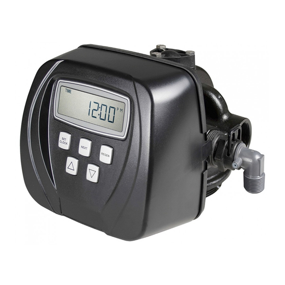
Page 4: Ci Front Cover And Drive Assembly
Page 4 CI Man u al CI Front Cover and Drive Assembly Drawing No. Order No. Description Quantity V3175CI-01 WS1CI FRONT COVER ASSEMBLY V3107-01 WS1 MOTOR V3106-01 WS1 DRIVE BRACKET & SPRING CLIP V3108CI-05BOARD WS1 THRU2L/2 CI PCB XMEGA REPL V3110 WS1 DRIVE REDUCING GEAR 12X36 V3109... -
Page 5: Oem General Instructions
CI Man u al Page 5 OEM General Instructions The control valve offers multiple procedures that allow the valve to be modifi ed to suit the needs of the installation. These procedures are: • OEM Cycle Sequence • OEM Softener System Setup •... -
Page 6: Oem Cycle Sequence
Page 6 CI Man u al OEM Cycle Sequence OEM Cycle Sequence instructions allows the OEM to set the order of Cycle Options the cycle. The OEM Softener System Setup or the OEM Filter System BACKWASH DN BRINE FILL Setup allow the OEM to set how long cycles will last. The OEM may choose up to 9 cycles in any order. - Page 7 Selection requires that a connection to MAV or a Clack No Hard Water Bypass Valve is made to the two pin connector labeled MAV located on the printed circuit board. If using a MAV, the A port of the MAV must be plugged and the valve outlet connected to the B port.
- Page 8 Once “Rinse” and “Fill” are completed, the valve will re-enter Standby mode until requested to come on-line for Service. For Clack Corporation alternator systems using the WS2 valve, Valve when NEXT is pressed after selecting ALT A or ALT b, a display will allow the user to set the amount of pre-service rinse time for the stand by tank just prior to returning to service.
- Page 9 Page 9 Confi guring the Control Valve to operate with Clack System Controller: Select SYS to link the Control Valve to the Clack System Controller. For communication between the Control Valve and the System Controller, a three-wire communication cable is required.
- Page 10 Page 10 CI Man u al STEP 6CS Step 6CS – Determine the measurement to calculate volumetric capacity. The choices are: parts per million French degrees German degrees NOTE: If control is going to be used in a fi lter application none of these settings can be used.
-
Page 11: Oem Softener System Setup
CI Man u al Page 11 OEM Softener System Setup In OEM Softener System Setup the OEM chooses the time for the cycles selected in OEM Cycle Sequence and specifi es other operating parameters for the system. The upper and lower limits of the allowable values for the cycles are as follows: Cycle Options Units Lower/Upper Limit... - Page 12 Page 12 CI Man u al Step 7S – Set System Capacity using ▼ or ▲. See chart. The System Setting Units STEP 7S Kg of Capacity setting should be based on the volume of resin and Kg of salt fi ll CaCO set in Step 6S.
-
Page 13: Setting Options Table
CI Man u al Page 13 Setting Options Table Filters should only use shaded options Volume Regeneration Time Result Capacity Option Override Reserve capacity automatically estimated. AUTO NORMAL Regeneration occurs when volume capacity falls below the reserve capacity at the next Regen Set Time. -
Page 14: Oem Filter System Setup
Page 14 CI Man u al OEM Filter System Setup In OEM Filter System Setup the OEM chooses the time for the cycles selected in OEM Cycle Sequence and specifi es other operating parameters for the system. The upper and lower limits of the allowable values for the cycles are as follows: Cycle Options Units Lower/Upper Limit... - Page 15 CI Man u al Page 15 Step 7F – Set Volume Capacity using ▼ or ▲. If value is set to: STEP 7F • “oFF” regeneration will be based solely on the day override set (see Installer Display/Settings Step 4I); or •...
-
Page 16: Installer Display Settings
Page 16 CI Man u al Installer Display Settings STEP 1I STEP 1I - Press NEXT and ▲ simultaneously for 3 seconds. STEP 2I – Hardness: Set the amount of infl uent hardness using ▼ or ▲. This display Units STEP 2I will show “–nA–”... -
Page 17: User Display Settings
CI Man u al Page 17 User Display Settings General Operation When the system is operating, one of fi ve displays may be shown. Pressing NEXT will alternate between the displays. One of the displays is always the current time of day. The second display is one of the following: days remaining or volume remaining. - Page 18 Page 18 CI Man u al Regeneration Mode Typically a system is set to regenerate at a time of low water usage. An example of a time with low water usage is when a household is asleep. If there is a demand for water when the system is regenerating, untreated water will be used.
- Page 19 CI Man u al Page 19 Salt Remaining or Adding Salt (not available for WS2 valves) If the Low Salt Warning was activated in the last step of OEM Softener System Setup the following screens will be viewed in the User Display.
-
Page 20: Diagnostics
Page 20 CI Man u al Diagnostics STEP 1D – Press ▲ and ▼ simultaneously for three seconds. If screen in step 2D does not appear STEP 1D in 5 seconds the lock on the valve is activated. To unlock press ▼, NEXT, ▲, and SET CLOCK in sequence, then press ▲... - Page 21 CI Man u al Page 21 STEP 7D – Flow rate, maximum last seven days: The maximum fl ow rate in liters per minute that STEP 7D occurred in the last seven days will be displayed. This display will equal zero if a water meter is not installed.
-
Page 22: Valve History
Page 22 CI Man u al Valve History STEP 1VH – Press ▲ and ▼ simultaneously for three seconds and release. Then press ▲ and ▼ STEP 1VH simultaneously and release. If screen in step 2VH does not appear in 5 seconds the lock on the valve is activated. -
Page 23: Revision History
CI Man u al Page 23 Revision History: 4/13/2012 PAGE 4: V3186 WS1 AC ADAPTER 120V-12V 12/18/2012 PAGE 4: V3108CI-05BOARD WS1 THRU2L/2 CI PCB XMEGA REPL Added new board drawing PAGE 6: Revised Step 2CS, 3CS and drawings PAGE 7: Revised Step 4CS PAGE 10: Revised Step 6CS, added Step 12CS... - Page 24 Page 24 CI Man u al 1/23/2013 PAGE 9: dPdEL – Revisions PAGE 13: Reserve Capacity estimate is based on history of water usage. Reserve Capacity estimate is not available with alternator systems or Twin Tank Valve. PAGE 20: STEP 5D - revised drawing PAGE 21: STEP 8D –...
Need help?
Do you have a question about the Water Specialist CI and is the answer not in the manual?
Questions and answers