Advertisement
Table of Contents
Advertisement
Table of Contents

Related Manuals for Clack Water Specialist EI


Summary of Contents for Clack Water Specialist EI
- Page 1 Water Specialist EI Control Valve Programming and Cover Drawing Manual...
- Page 2 Page 2 EI Man u al...
-
Page 3: Table Of Contents
EI Man u al Page 3 Table of Contents EI Front Cover and Drive Assembly ........................... 4 Regeneration and Error Screens ............................5 User Displays ..................................6 Confi guration Settings ................................ 7 OEM Softener System Setup ............................11 Setting Options Table ................................ 14 OEM Filter System Setup .............................. -
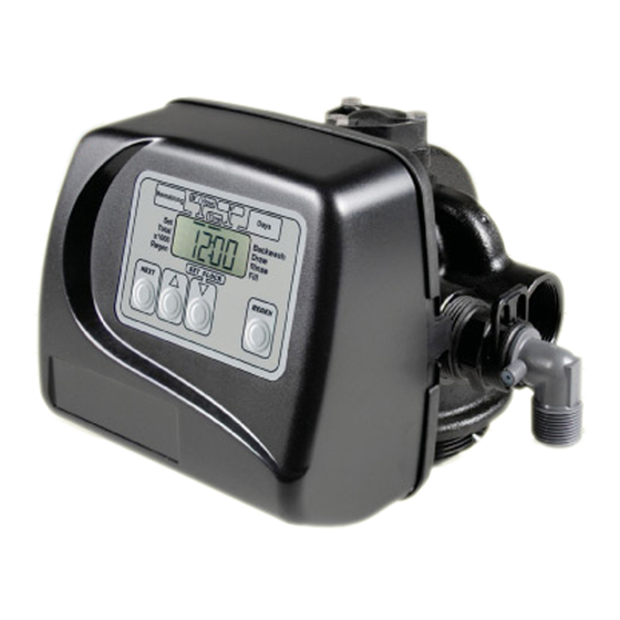
Page 4: Ei Front Cover And Drive Assembly
Page 4 EI Man u al EI Front Cover and Drive Assembly Drawing No. Order No. Description Quantity V3175EE-01 WS1EE FRONT COVER ASSEMBLY V3107-01 WS1 MOTOR V3002-A WS1 DRIVE BRACKET ASY V3408EI-04BOARD WS1THRU2 EI PCBRD 5 DIGIT REPL V3110 WS1 DRIVE REDUCING GEAR 12X36 V3109 WS1 DRIVE GEAR COVER V3106-01... -
Page 5: Regeneration And Error Screens
EI Man u al Page 5 Regeneration and Error Screens Regen Screen Displays the time remaining in the current cycle. Pressing REGEN advances to the next cycle. Error Screen Alternated fl ashing Err and error code every 3 seconds. Clear by disconnecting the power supply at the PC board and reconnecting, or press NEXT and REGEN simultaneously for 3 seconds. -
Page 6: User Displays
Page 6 EI Man u al User Displays General Operation When the system is operating, one of fi ve displays may be shown. Pressing NEXT will alternate between the displays shown below. User 1 Typical user display. Shows volume remaining to regeneration. This screen will not be viewed if the control is set for time-clock operation. -
Page 7: Confi Guration Settings
EI Man u al Page 7 Confi guration Settings Step 1CS – Press NEXT and ▼ simultaneously for 5 seconds and release. Press NEXT and ▼ Step 1CS simultaneously for 5 seconds and release. If the screen in Step 2CS does not appear, the lock on the valve is activated. - Page 8 Select OFF when none of these features are used. Only use Clack No Hard Water Bypass Valves or Clack Motorized Alternating Valves (MAV) with these selections. Clack No Hard Water Bypass Valves (1” or 1.25” V3070FF or V3070FM) are not designed to be used with the alternator or separate source functions.
- Page 9 Page 9 WS1, WS1.25 and WS1.5 Valves For Clack Corporation alternator systems using WS1, WS1.25 and WS1.5 valves there will be an option to delay the last two cycles of regeneration (only “Rinse” and “Fill”). This feature splits the regeneration into two portions.
- Page 10 System Controller, a three-wire communication cable is required. Selection requires that a connection to a Clack No Hard Water Bypass (V3070FF or V3070FM) be made to the two-pin connector labeled MAV located on the printed circuit board for WS1 and WS1.25 control valves.
-
Page 11: Oem Softener System Setup
EI Man u al Page 11 OEM Softener System Setup Step 1S - Press NEXT and ▼ simultaneously for 5 seconds and release. If screen in Step 2S does not Step 1S appear, the lock on valve programming has been activated. To unlock press ▼, NEXT, ▲, REGEN in sequence, then press NEXT and ▼... - Page 12 Page 12 EI Man u al Step 9S – Select the kg for the fi fth cycle using ▲ or ▼. Step 9S NOTE: if Step 2CS is set to 2.0 or Step 7CS is set to MIN, Fill will be in minutes. Press NEXT to go to Step 10S.
- Page 13 EI Man u al Page 13 Step 14S – Set Relay Actuation Time or Liters using ▲ or ▼. The choices are: Step 14S • Relay Actuation Time: After the start of a regeneration the amount of time that should pass prior to activating the relay.
-
Page 14: Setting Options Table
Page 14 EI Man u al Setting Options Table Filters should only use shaded options Volume Regeneration Time Result Capacity Option Override Reserve capacity automatically estimated. AUTO NORMAL Regeneration occurs when volume capacity falls below the reserve capacity at the next Regen Set Time. -
Page 15: Oem Filter System Setup
EI Man u al Page 15 OEM Filter System Setup Cycle Sequence, Adjustable Default Times (minutes) Type Backwash Draw Backwash Rinse Backwash* Fill Filtering Backwash Filtering Regen 0:30 4.2 L Filtering Regen (2.0”) 0:30 *Cycle is non-adjustable, not shown in cycle sequence programming. Step 1F - Press NEXT and ▼... - Page 16 Page 16 EI Man u al Step 7F – Set Relay Operation using ▲ or ▼. The choices are: Step 7F • Time on: Relay activates after a set time at the beginning of a regeneration and then deactivates after a set period of time. The start of regeneration is defi...
-
Page 17: Installer Display Settings
EI Man u al Page 17 Installer Display Settings Step 1I - To enter Installer Display press NEXT and ▲ simultaneously for about 5 seconds and release. Step 1I Step 2I – Hardness: Set the amount of infl uent hardness using ▲ or ▼. This display will not be viewed if Step 2I FILTERING BACKWASH or FILTERING REGEN is selected in Step 2F OR if “oFF”... -
Page 18: Diagnostics
Page 18 EI Man u al Diagnostics Step 1D - Press ▲ and ▼ simultaneously for 5 seconds and release. If screen in Step 2D does not appear Step 1D the lock on the valve is activated. To unlock press ▼, NEXT, ▲, REGEN in sequence, then press ▲ and ▼ simultaneously for 5 seconds and release. - Page 19 EI Man u al Page 19 Step 9D – Volume, reserve capacity used for last 7 days: If the valve is Step 9D set up as a softener, a meter is installed, and Set Volume Capacity is set to “Auto,” this display shows day 0 (for today) and fl ashes the reserve capacity.
- Page 20 Page 20 EI Man u al...
- Page 21 EI Man u al Page 21...
- Page 22 Page 22 EI Man u al...
-
Page 23: Revision History
EI Man u al Page 23 Revision History: 3/12/2015 PAGE 12: Step 13S – Clarifi ed relay operation PAGE 16: Step 7F – Clarifi ed relay operation 11/16/2016 PAGE 17: Step 3I – updated text 8/24/2017 PAGE 4: Updates to table and drawing - Bracket and Spring Clip / Power Supply... - Page 24 Page 24 EI Man u al Form No. V3435EI – 8/24/2017 U.S. Patents: 6,402,944 • 6,444,127 • 6,776,901...
Need help?
Do you have a question about the Water Specialist EI and is the answer not in the manual?
Questions and answers