
Related Manuals for Rosemount 148


Summary of Contents for Rosemount 148
- Page 1 Quick Start Guide 00825-0100-4148, rev. DA April 2013 Rosemount 148 Temperature Transmitter...
-
Page 2: Table Of Contents
Quick Start Guide NOTICE This installation guide provides basic guidelines for the Rosemount 148. It does not provide instructions for detailed configuration, diagnostics, maintenance, service, troubleshooting, or installations. Refer to the Rosemount 148 Reference Manual (Document No. 00809-0100-4148) for more instruction. The manual and this QIG are also available electronically on www.rosemount.com. -
Page 3: Software Installation
Run setup.exe from Windows NT, 2000, or XP 2. When first using the 148 PC software, configure the appropriate COM ports by selecting “Port Settings” from the “Communicate” menu. 3. Install MACTek Modem drivers completely before beginning bench configuration on the Rosemount 148 system. -
Page 4: Mount The Transmitter
April 2013 Quick Start Guide Step 3: Mount the transmitter To prevent moisture from draining into the transmitter housing, mount the transmitter at a high point in the conduit run. Typical European and Asia Pacific installation Head Mount Transmitter with DIN plate style sensor 1. - Page 5 Quick Start Guide April 2013 Step 3 continued... A = Rosemount 148 Transmitter D = Transmitter Mounting Screws B = Connection Head E = Integral Mount Sensor with Flying Leads C = Thermowell F = Extension Typical North and South American installation Head Mount Transmitter with Threaded Sensor 1.
- Page 6 B = Threaded Style Sensor E = Conduit Entry C = Standard Extension Mounting to a DIN Rail Mounting Hardware To attach the Rosemount 148H to a DIN rail, assemble the appropriate rail mounting kit (part number Transmitter 00248-1601-0001) to the transmitter as shown.
-
Page 7: Connect The Wiring
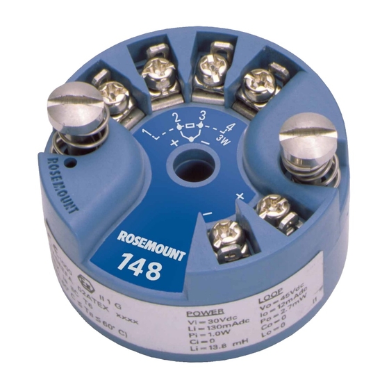
Quick Start Guide April 2013 Step 4: Connect the wiring Wiring diagrams are located on the top label of the transmitter. An external power supply is required to operate the transmitter. The power required across the transmitter power terminals is 12 to 42.4 Vdc ... - Page 8 April 2013 Quick Start Guide Step 4 continued... Option 1 (for grounded housing): 1. Connect sensor wiring shield to the transmitter housing. 2. Ensure the sensor shield is electrically isolated from surrounding fixtures that may be grounded. 3. Ground signal wiring shield at the power supply end. Transmitter 4–20 mA loop Sensor Wires...
- Page 9 Quick Start Guide April 2013 Step 4 continued... Option 3 (for grounded or ungrounded housing): 1. Ground sensor wiring shield at the sensor, if possible. 2. Insure that the sensor wiring and signal wiring shields are electrically isolated from the transmitter housing. 3.
-
Page 10: Product Certifications
Rosemount Inc. complies with the ATEX Directive. Electro Magnetic Compatibility (EMC) (89/336/EEC) All Models: EN 50081-1: 1992; EN 50082-2: 1995; EN 61326-1: 2006 – Industrial NAMUR NE21 Recommendations The Rosemount 148 meets the requirements for NAMUR NE21 Rating Susceptibility Parameter Influence... -
Page 11: Hazardous Locations Certifications
Certificate No: 1091070 C22.2 No. 0-M10, C22.2 No. 142-M1987, C22.2 No. 157-92, C22.2 No. 213-M1987. Intrinsically Safe for Class I, Division 1, Groups A, B, C, D when installed per Rosemount drawing 00148-1056. Suitable for Class I, Division 2, Groups A, B, C, D +60 °C) - Page 12 April 2013 Quick Start Guide European Certifications I1 ATEX Intrinsic Safety Certificate No: BASEEFA08ATEX0030X EN 60079-0:2006, EN 60079-11:2007 II 1 G Ex ia IIC T5 (-60 ° T +80 °C) T6 (-60 ° T +60 °C) Entity Parameters: Loop/Power Sensor = 30 Vdc...
- Page 13 Quick Start Guide April 2013 N1 ATEX Type N Certificate No: BAS00ATEX3145 EN 60079-0:2006, EN 60079-15:2005 II 3 G Ex nL IIC T5 (-40 ° T +70 °C) Umax = 45V NC ATEX Type n Component Certificate No: BASEEFA08ATEX0031U EN 60079-0:2006, EN 60079-15:2005 II 3 G Ex nA IIC T5 (-60°Ta+80°C)
- Page 14 April 2013 Quick Start Guide Brazilian Certifications E2 NCC Explosion-proof Certificate No: NCC 12.1147X Ex d IIC Gb T6 (-40°C Ta +65°C) Special Conditions for Safe Use (X): 1. For information on the dimensions of the flameproof joints the manufacturer shall be contacted.
- Page 15 Quick Start Guide April 2013 I7 IECEx Intrinsic Safety Certificate No: IECEx BAS 08.0011X IEC 60079-0:2004, IEC 60079-11:2006 Ex ia IIC T5 (-60 ° Ta +80 °C) T6 (-60 ° Ta +60 °C) Entity Parameters: Loop / Power Sensor = 30 Vdc = 45 Vdc...
- Page 16 April 2013 Quick Start Guide Measuring Instruments Directive Parts Certification The Rosemount 3144P Temperature Transmitter and Rosemount 0065 RTD Temperature Sensor have been certified to meet the European Union Measurement Instrument Directive (MID) for Custody Transfer metering of liquids and gases.
-
Page 17: 148 Pc Programmer License Agreement
Software. TITLE: Licensee agrees that the Software, Documentation and all copies, in whole or part, thereof are and shall remain the sole property or Rosemount Inc., or its third party suppliers. COPYRIGHT: The Software contains programs that are owned by Rosemount Inc. - Page 18 Software. In no event, whether in an action at law or in equity and regardless of the form of the claim, shall Rosemount Inc. be liable for: (a) any and all special, incidental, indirect, or consequential damages;...
- Page 19 Quick Start Guide April 2013 under this Agreement between Rosemount Inc. and Licensee. Rosemount Inc. pricing reflects this allocation of risk and the limitation of liability specified herein. GOVERNING LAW: The laws of the State of Minnesota shall govern as to the...
- Page 20 EC Declaration of Conformity No: RMD 1070 Rev. A Rosemount Inc. 8200 Market Boulevard Chanhassen, MN 55317-6985 declare under our sole responsibility that the product, Model 148 Temperature Transmitter manufactured by, Rosemount Inc. 12001 Technology Drive 8200 Market Boulevard Eden Prairie, MN 55344-3695...
- Page 21 Quick Start Guide April 2013 Schedule EC Declaration of Conformity RMD 1049 Rev. A.3 EMC Directive (2004/108/EC) Model 148 Temperature Transmitter EN 61326: 1997 + A1/A2/A3 – Industrial ATEX Directive (94/9/EC) Model 148 Temperature Transmitter Baseefa08ATEX0030X – Intrinsically Safe Certificate Ex ia IIC: EN 60079-0: 2006;...
- Page 22 T 49 (8153) 9390, F49 (8153) 939172 Beijing Rosemount Far East © 2013 Rosemount Inc. All rights reserved. All marks property of owner. Instrument Co., Limited The Emerson logo is a trade mark and service mark of Emerson Electric Co No.
Need help?
Do you have a question about the 148 and is the answer not in the manual?
Questions and answers