Table of Contents
Advertisement
Quick Links
CU3-01M, CU3-02M
Central unit
EN
Characteristics
- CU3-01M and CU3-02M are central units' of the iNELS system and mediators, between user software interface and controllers, units and actuators connected to the BUS.
- It's possible to directly connect up to 2 lines of BUSes in to CU3-01M and CU3-02M, and on each BUS we can connect up to 32 iNELS3 units.
- The main diff erence between CU3-02M and CU3-01M is that CU3-02M is moreover equipped by RF module which enables communication with selected units from iNELS RF Control system.
- Central units CU-01M (02M) support also peripheral units from iNELS2 thanks to external master MI3-02M/iNELS2.
- User´s project and retentive data are stored in a non-volatile internal memory hereby data are backed up without the supply voltage. Real time clock (RTC) backup for 10 days.
- Power supply controlling system - network voltage and the status of the backup battery.
- Possibility of setting time synchronization via NTP server.
- The RJ45 Ethernet port's connector is located on the front panel of the unit, the transmission speed is 100 Mbps.
- For CU3-01M (02M) it is possible to use 4 potential-free inputs for connecting external controllers (buttons, switches, sensors, detectors, etc.) and 2 analog inputs 0 - 30V.
- CU3-01M (02M) comes with OLED display that shows the current status and enables settings (network settings, date, time, service) of the central unit CU3-01M (02M).
- Movement in the menu CU3-01M (02M) using arrows on the front panel.
- CU3-01M (02M) in 6-MODULE are designed for mounting into a switchboard on the EN60715 DIN rail.
Installation BUS:
- Two-wired BUS with an arbitrary topology (not only to be as closed circle).
- With its own modulated communications on the DC voltage supply.
- One line of BUS allows you to connect up max. 32 units of iNELS3, or iNELS2 if you use external master MI3-02M/iNELS2.
- The current load of one line is max. 1A.
- Maximum length of the BUS is approximately 550 m (depends on the voltage drop).
- Recommended cable:
- iNELS BUS Cable - Twisted pair of copper wires with size of AWG20 wire (diameter of 0.812 mm, cross-section of 0.5190 mm
- Used to connect the CU3-01M(02M) central unit with MI3-02M external masters, MI3-02M/iNELS2, GSM communicator GSM3-01M or converter DALI/DMX EMDC-64M.
- EBM has strictly linear topology and wires are connected to terminals EBM + and EBM-, wires can not be interchanged.
- Max. length of the line of BUS is 500 m.
- The EBM BUS has to be terminated at both ends.
- This part adapted to be inserted between terminals is included into central units packages and it is necessary to insert between terminals EBM+ and EBM-.
- Reccomended cabling:
- CAT5e UTP and higher, or FTP CAT5e and higher or STP CAT5e and higher.
- The confi gurations of units and the whole system are done via Ethernet, through confi guration software - iNELS3 Designer & Manager (iDM3), which is designed for operating systems Windows 7, Windows
8 and Windows 10.
- The central unit features two communication protocols:
- ELKONET - to communicate with iMM and Connection Server or directly with the application iHC.
- ASCII - communication with third systems and integration with BMS (Building Management Systems), for example Niagara 4.
- Supported Software:
- Parameterization, confi guration, control and visualization:
iNELS3 Designer & Manager (iDM3).
- By means of iDM3, you can update fi rmware of central units and peripheral units connected by BUS.
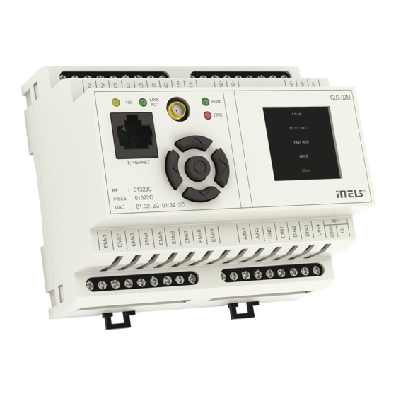
Description of device
1
2
3
4
5
6
2
).
1. Data BUS1
7
2. Supply voltage terminals
8
3. LED indication Ethernet speed 100 Mbps
4. LED indication for Ethernet communication
9
5. Ethernet port 100 Mbps (RJ45)
6. Analog inputs 0-30 V DC
10
7. Data BUS2
11
12
13
14
8. System BUS EBM
9. SMA antenna connector (CU3-02M)
10. Operational state of unit LED indication
11. Information display
12. Routing buttons
13. Relay output NO/GND
14. Digital inputs
1/3
Advertisement
Table of Contents

Subscribe to Our Youtube Channel
Related Manuals for iNels CU3-01M


Summary of Contents for iNels CU3-01M
- Page 1 - CU3-01M and CU3-02M are central units’ of the iNELS system and mediators, between user software interface and controllers, units and actuators connected to the BUS. - It‘s possible to directly connect up to 2 lines of BUSes in to CU3-01M and CU3-02M, and on each BUS we can connect up to 32 iNELS3 units.
- Page 2 Number of connected units (directly to the max. 64 (2x32) CU3-01M (02M): Expansion possibilities external BUS master: up to 576 units (CU3-01M (02M) and 8x MI3-02M) Communication Maximum number of units: max. 32 units to one BUS line Maximum cable length: max.
- Page 3 BUS installation. Installation BUS conductors are connected to the terminal units to BUS + and BUS-terminals, wires cannot be interchanged. For installation of BUS it is necessary to use a cable with a twisted pair of wires with a diameter of at least 0.8 mm, the recommended cable is iNELS BUS Cable, whose features best meet the requirements of the BUS installation.
Need help?
Do you have a question about the CU3-01M and is the answer not in the manual?
Questions and answers