Table of Contents
Advertisement
Quick Links
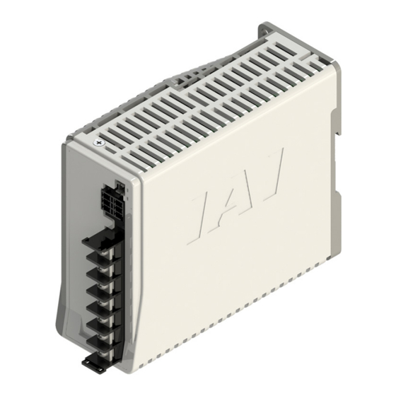
24V Power Supply Unit
Instruction Manual
PSA-24
First Edition
ME0379-1A
Specifications
Installation
Wiring
Operation
Preventive/Predictive
Maintenance
Before Considering
Failure
Maintenance and
inspection
External Dimensions
Life
Warranty
Appendix
1
Chapter
2
Chapter
3
Chapter
4
Chapter
5
Chapter
6
Chapter
7
Chapter
8
Chapter
9
Chapter
10
Chapter
11
Chapter
Advertisement
Table of Contents

Subscribe to Our Youtube Channel
Related Manuals for IAI PSA-24

Summary of Contents for IAI PSA-24
- Page 1 PSA-24 24V Power Supply Unit Instruction Manual First Edition ME0379-1A Specifications Chapter Installation Chapter Wiring Chapter Operation Chapter Preventive/Predictive Chapter Maintenance Before Considering Chapter Failure Maintenance and Chapter inspection External Dimensions Chapter Life Chapter Warranty Chapter Appendix Chapter...
-
Page 2: Part Names ·····················································································
● This instruction manual is an original document dedicated for this product. ● This product cannot be used in ways not shown in this instruction manual. IAI shall not be liable for any result whatsoever arising from the use of the product in any other way than what is noted in the manual. - Page 3 PSA-24 Power Supply Unit Instruction Manual Configuration Control Product name Instruction manual name number 24V Power Supply Unit PSA-24 First Step Guide ME0380 24V Power Supply Unit PSA-24 Instruction Manual (this document) ME0379...
-
Page 4: Table Of Contents
Contents Safety Guide ·················································································· Intro-1 Precautions for Handling ···································································· Intro-8 International Standard Compliance ······················································· Intro-9 EMC specifications ····················································································· Intro-9 Safety standard specifications ······································································· Intro-10 Part Names ····················································································· Intro-11 Functions of each part ················································································· Intro-13 Chapter 1 Specifications 1.1 Product Configuration ··································································· 1-1 Components ··································································································... - Page 5 Chapter 5 Preventive/Predictive Maintenance 5.1 Preventive Maintenance Function ··················································· 5-1 Connection method ························································································· 5-1 Status data ···································································································· 5-2 Fan installation ······························································································· 5-2 Chapter 6 Before Considering Failure 6.1 Before Considering Failure ···························································· 6-1 Chapter 7 Maintenance and Inspection 7.1 Maintenance and Inspection ·························································· 7-1 Precautions for inspection ················································································...
-
Page 7: Safety Guide
Safety Guide Safety Guide The Safety Guide is intended to permit safe use of the product and thus to prevent risks and property damage. Be sure to read it before handling the product. Safety Precautions for Our Products Common safety precautions for the use of robots in various operations are indicated here. Operation Precautions ●... - Page 8 Safety Guide Operation Precautions ● When transporting heavy objects, do the work with two or more persons or Transportation utilize equipment such as a crane. ● When working with two or more persons, make it clear who is to be in charge and communicate well with each other to ensure safety.
- Page 9 Safety Guide (2) Cable wiring ● Use IAI genuine cables for connecting the actuator and controller, and for the teaching tools. ● Do not scratch cables, bend them forcibly, pull them, coil them, snag them, or place heavy objects on them. Otherwise, this may lead to fire, electric shock, or abnormal operation due to leakage or conduction malfunction.
- Page 10 Safety Guide Installation (4) Safety measures ● When working with two or more persons, make it clear who is to be in charge Startup and communicate well with each other to ensure safety. ● When the product is operating or in the ready mode, take safety measures (such as the installation of safety/protection fences) so that nobody can enter the area within the robot's movable range.
- Page 11 Safety Guide ● When working with two or more persons, make it clear who is to be in charge Trial Operation and communicate well with each other to ensure safety. ● After teaching or programming, carry out trial operation step by step before switching to automatic operation.
- Page 12 Safety Guide ● When working with two or more persons, make it clear who is to be in charge Maintenance and communicate well with each other to ensure safety. ● Perform the work outside the safety/protection fence, if possible. If operation Inspection must be performed within the safety/protection fence, prepare "Work Regulations"...
- Page 13 Safety Guide Precaution Indications The safety precautions are divided into "Danger", "Warning", "Caution" and "Notice" according to the warning level, as follows, and described in the Instruction Manual for each model. Level Degree of risk to persons and property Symbol This indicates an imminently hazardous situation which, if the product Danger Danger...
-
Page 14: Precautions For Handling
Do not attempt any handling or operation that is not indicated in this instruction manual. PSA-24 Power Supply is a power supply unit dedicated for IAI controllers which utilize 24 VDC. Specifications include a wide input voltage range of 100 VAC to 230 VAC. -
Page 15: International Standard Compliance
International Standard Compliance International Standard Compliance EMC specifications This power supply unit satisfies the following EMC specifications. Item Condition Specifications ±2000 V Pulse width (100/1000 ns, repeating Noise-resistance ability No output DC fluctuations or cycle 30-100Hz, normal/common (Impulse noise test) malfunctions mode, 10-minute positive/negative polarity switching) -
Page 16: Safety Standard Specifications
International Standard Compliance Safety standard specifications This power supply unit meets the following safety standards. Item Standards UL/cUL UL61010-1 CE Marking LVD: EN61010 / EMC: EN55011 Intro-10... -
Page 17: Part Names
Part Names Part Names PSA-24 (204W / without fan) PSA-24L (330W / with fan) Intro-11... - Page 18 Part Names Fan unit Fan alarm notification LED Fan connector Communication connector Normal operation notification LED Communication address switch Power terminal block Front DIN tab Screw mounting hole Left side Right side Rear Intro-12...
-
Page 19: Functions Of Each Part
Part Names Functions of each part [Fan alarm notification LED / normal operation notification LED] This power supply unit is equipped with the following two kinds of LED. Name Panel notation Display color Status Description Light ON Fan rotation speed abnormality Fan alarm notification Orange... - Page 20 Part Names [Power terminal block] Terminal block for AC power supply input, frame ground, and output voltage wire connections. OUTPUT DC24V 13.8A INPUT 100 ~ 230VAC 50/60Hz 3.9A Connector name: DT-5C-B84W-6717-07 (DINKLE) Pin No. Signal Description +24 V 24V output terminal (Pins 1 and 2 are internally connected) +24 V 0V output terminal (Pins 3 and 4 are internally connected) Frame ground terminal (ground terminal connected to power supply housing)
- Page 21 Part Names [Communication connector] Connector for monitoring status data inside the power supply by communication. In order to enable communication of multiple power sources by multi-drop, two connection ports are provided. The differential signal of each connection port is short-circuited, so any port can be used for connection.
- Page 22 Part Names [Fan connector] Fan connector used when continuous rated output is at 330 W. Board-side connector name: DF11-4DP-2DS(24) (HIROSE) Pin No. Signal Description 24 V Fan power supply CONNECT Connection recognition signal (Connected: H / Not connected: L) Fan GND PULSE Fan rotation speed pulse Intro-16...
-
Page 23: Specifications
Power supply unit Chapter Specifications 1.1 Product Configuration ············································· 1-1 Components ·································································· 1-1 How to read the model nameplate ····································· 1-1 Model name ·································································· 1-2 1.2 General Specifications ············································ 1-3 Input specifications ························································· 1-3 Output specifications ······················································· 1-4 Protective function specifications ······································· 1-5 Insulation specifications ···················································... -
Page 24: Product Configuration
1.1 Product Configuration The standard configuration of this product is comprised of the following parts. In the unlikely case that any model number errors or missing parts come to light, contact your local IAI distributor. Components Part name Model number Refer to "How to read the model... -
Page 25: Model Name
· 24: 24 V power supply unit · FU: Fan unit (Single) (2) Option with fan · Blank: Standard specification (204W) · L: Unit with fan specification (330W) * If the fan unit PSA-FU is retrofitted to the PSA-24, it can be used at 330W. -
Page 26: General Specifications
1.2 General Specifications 1.2 General Specifications Input specifications Item Specifications Terms of use, etc. Power input voltage 100 VAC to 230 VAC ±10% range Continuous rated 2.5A or less output 204 W 100 VAC Continuous rated 3.9A or less output 330 W Power supply current Continuous rated... -
Page 27: Output Specifications
*1: In order to enable parallel operation, this power supply can vary the output voltage according to the load. Therefore, the power supply unit is dedicated for IAI controllers. Refer to "Output voltage" on page 4-1 for the characteristics of output voltage by load. -
Page 28: Protective Function Specifications
1.2 General Specifications Protective function specifications Item Specifications Output is cut off when a current exceeding the peak capacity flows (including short circuits) Operation Refer to "Output voltage" on page 4-1 Overcurrent Protection Intermittent action during dip protection method Recovery Automatic recovery Operation Output is cut off when overheating is detected by the temperature sensor on the circuit board Overheat Protection... -
Page 29: Insulation Specifications
1.2 General Specifications * 2: When fan connection is detected at startup, it can be used at continuous rated output 330 W by switching the overload protection level. The overload protection level is decreased in case of fan malfunction, so the continuous rated output is restricted to 204W. Insulation specifications Item Condition... - Page 30 1.2 General Specifications...
-
Page 31: Chapter 2 Installation
Power supply unit Chapter Installation 2.1 Environmental Conditions ········································ 2-1 2.2 Heat Dissipation and Mounting ································· 2-3... -
Page 32: Environmental Conditions
2.1 Environmental Conditions 2.1 Environmental Conditions Item Specifications Terms of use, etc. Ambient operating 0°C~+55°C Natural air cooling (204 W/without fan) temperature (With derating) Forced cooling (330 W/with fan) Ambient operating 85% RH or less non-condensing humidity Ambient storage -20°C~+70°C temperature Atmosphere Avoid corrosive gas and excessive dust... - Page 33 2.1 Environmental Conditions Reduce the output power in accordance with the following derating curve at high temperatures. PSA-24 output derating graph 100 V Series 200 V Series Temperature [°C] PSA-24L output derating graph 100 V Series 200 V Series Temperature [°C] Figure 2.1.1 Derating with regard to ambient temperature...
-
Page 34: Heat Dissipation And Mounting
2.2 Heat Dissipation and Mounting 2.2 Heat Dissipation and Mounting Item Specifications Installation direction Horizontally mounted Installation Installation method Screw mounted or DIN rail mounted Ground Independent grounding via class D grounding Restrictions in ambient environment Refer to Figure 2.2.3 *1: The only possible installation orientation is below. - Page 35 ● PSA-24 100mm or more 10mm 10mm or more or more 100mm or more 50mm or more Figure 2.2.3a Restrictions in ambient environment (PSA-24) ● PSA-24L 100mm or more Power supply interval 10mm minimum zero or more 100mm or more 50mm or more Figure 2.2.3b Restrictions in ambient environment (PSA-24L)
- Page 36 2.2 Heat Dissipation and Mounting...
- Page 37 Power supply unit Chapter Wiring 3.1 Connection to Peripheral Devices (Overall Electrical Wiring Diagram) ····· 3-1 3.2 Connection Cables ················································· 3-2 Communication cable ······················································ 3-2 Power supply cable ························································ 3-3...
-
Page 38: Connection To Peripheral Devices (Overall Electrical Wiring Diagram)
3.1 Connection to Peripheral Devices (Overall Electrical Wiring Diagram) 3.1 Connection to Peripheral Devices (Overall Electrical Wiring Diagram) Fan unit Communication connector included with power supply Cable to be prepared by user RCON (Prepared by user) AC cable to be prepared by user -... -
Page 39: Connection Cables
3.2 Connection Cables 3.2 Connection Cables Communication cable This shows the applicable wire and strip length that can be used for the cable connector. Use twisted pair cables for differential signal lines. Cable side connector name 0221-2403 (DINKLE) Core wire Strip length Item Specifications... -
Page 40: Power Supply Cable
3.2 Connection Cables Power supply cable The following shows the specifications for terminals and wiring for connections. Item Specifications Terminal block screw diameter M3.5 Rated torque 1.1 [N·m] Applicable round terminal 1.25-M3.5 (AWG22 ~ 16) (applicable wire size) 2-M3.5 (AWG16 ~ 14) Recommended wire size AWG14 ~ 18 The number of crimped terminals connected at the same time per terminal screw should be 2 or... - Page 41 Power supply unit Chapter Operation Specification Details ············································· 4-1 Output voltage ······························································· 4-1 Parallel operation ··························································· 4-3 Power ON/OFF sequence ················································ 4-6 Inrush current prevention circuit ········································ 4-7 Overload detection ························································· 4-8 Signal line ····································································· 4-9...
-
Page 42: Specification Details
IAI 24 V controllers. Although the operation range differs between PSA-24 (204 W) and PSA-24L (330 W), the output voltage fluctuates within the range of the shaded area in both cases. The output voltage is cut off by the protection circuit if the overvoltage detection level is exceeded. - Page 43 4.1 Specification Details Overcurrent ● PSA-24L detection Approx. 18 A Output current [A] Figure 4.1.2 Output voltage fluctuation due to load (PSA-24L)
-
Page 44: Parallel Operation
■ Parallel operation should be limited to 5 units. Do not connect power supply units other than PSA-24 in parallel. ■ Do not operate PSA-24 (204 W) and PSA-24 L (330 W) in parallel. ■ When performing parallel operation, turn on all AC inputs of the connected power supply units at the same time. - Page 45 4.1 Specification Details ● For one load Take out to the common terminal block and configure for parallel connection. The common terminal block is used to connect all power supply lines in this case, eliminating the need to run cables between power supply units. Variations in the output current of each power supply unit can be better suppressed if not connecting on the power supply side.
- Page 46 4.1 Specification Details If one load is connected without using the terminal block as shown in the figure below, the load current for the power supply unit closer to the load increases and the voltage drop due to the cables becomes larger, creating an unbalanced output current. To balance the cable voltage drop, always take out with the terminal block as shown in Figure 4.1.4 before connecting the load.
-
Page 47: Power On/Off Sequence
4.1 Specification Details Power ON/OFF sequence The startup time and output retention time stipulated in "Output specifications" on page 1-4 define the following times. Input cutoff Constant voltage precision range 24V ±10% Input ON Startup time Output retention time Item Specifications Startup time The time until the output voltage rises to 90% after the input voltage is applied... -
Page 48: Inrush Current Prevention Circuit
4.1 Specification Details Inrush current prevention circuit This power supply unit uses a thermistor to suppress inrush current at startup. The thermistor has high resistance at low temperatures and low resistance at high temperatures. Therefore, when the power is turned on, the inrush current is suppressed by the high resistance, but as power is supplied the temperature rises and the resistance decreases, reducing the loss due to the thermistor. -
Page 49: Overload Detection
In this range, an overload error occurs after a certain time depending on the current value. ● PSA-24 Overload detection Overcurrent detection Approx. 9.8 A Approx. 18 A Overload detection range Output current [A] Figure 4.1.5 Overload detection range (PSA-24) -
Page 50: Signal Line
Output current [A] Figure 4.1.6 Overload region (PSA-24L) Signal line Signal lines when connecting with RCON are shown below. Modbus Fieldbus PSA-24 RCON Modbus PSA-24 Fig. 4.1.7 Signal lines Up to 5 units can be connected with RCON via daisy chain. - Page 51 Power supply unit Chapter Preventive/Predictive Maintenance 5.1 Preventive Maintenance Function ····························· 5-1 Connection method ························································ 5-1 Status data ··································································· 5-2 Fan installation ······························································ 5-2...
-
Page 52: Preventive Maintenance Function
This method connects the RCON gateway board to the power supply unit and monitors the power supply unit status data via RCON. To monitor status data using RC software (PSA-24 compatible version), connect using the RCON USB interface. The status data of the power supply is also available on the fieldbus, so it is possible to monitor the status data from the host network via PLC. -
Page 53: Status Data
5.1 Preventive Maintenance Function Status data The status data that can be monitored is as follows. Item Content AD conversion value of output voltage. This power supply fluctuates the Output voltage output voltage according to the load, so the output voltage monitor value changes from time to time, but this is not abnormal. - Page 54 5.1 Preventive Maintenance Function ● Switch overload error threshold The rated current changes depending on whether a fan is connected or not, so the internal overload error threshold is also switched after detecting the fan connection. If fan abnormal rotation speed is detected, there is a possibility of significant decrease in life or failure of continuous operation, so the threshold value for overload error will be forcibly switched to the threshold for continuous rated output 204W (without fan).
-
Page 55: Before Considering Failure
Power supply unit Chapter Before Considering Failure 6.1 Before Considering Failure ······································ 6-1... - Page 56 6.1 Before Considering Failure 6.1 Before Considering Failure Content Countermeasures • Is the specified input voltage connected? • Is there a short circuit or ground fault in the output circuit? • Has the power supply unit been rebooted immediately after the No output voltage overvoltage circuit / overheat protection circuit activated? •...
-
Page 57: Chapter 7 Maintenance And Inspection
Power supply unit Chapter Maintenance and Inspection 7.1 Maintenance and Inspection····································· 7-1 Precautions for inspection ················································ 7-1... -
Page 58: Precautions For Inspection
7.1. Maintenance and Inspection 7.1 Maintenance and Inspection Precautions for inspection ● Because there are heat generating parts inside the power supply unit die cast section and interior, perform inspection after allowing sufficient cooling time after turning OFF the power supply unit. -
Page 59: Chapter 8 External Dimensions
Power supply unit Chapter External Dimensions 8.1 External Dimensions ··············································· 8-1... - Page 60 8.1. External Dimensions 8.1 External Dimensions Item Specifications PSA-24 54(W) x 115(H) x 140(D) External dimensions PSA-24L 54(W) x 131(H) x 140(D) PSA-24 805g Weight PSA-24L 845g PSA-FU...
- Page 61 8.1. External Dimensions PSA-24 39.6 35.2 ϕ5...
- Page 62 8.1. External Dimensions PSA-24L 55.6 35.2 (21) ϕ5...
-
Page 63: Chapter 9 Life
Power supply unit Chapter Life 9.1 Consumable Parts·················································· 9-1... -
Page 64: Consumable Parts
9.1 Consumable Parts 9.1 Consumable Parts Item Life Conditions Electrolytic capacitor 5 years Ambient temperature 40°C Continuous rated output 3 years... - Page 65 Power supply unit Chapter Warranty 10.1 Warranty Period ··················································· 10-1 10.2 Scope of the Warranty ··········································· 10-1 10.3 Honoring the Warranty ·········································· 10-1 10.4 Limited Liability ···················································· 10-2 10.5 Conformance with applicable standards/regulations, etc., and application conditions ······························ 10-2 10.6 Other items excluded from warranty ······················· 10-2...
-
Page 66: Warranty Period
Our products are covered by warranty when all of the following conditions are met. Faulty products covered by warranty will be replaced or repaired free of charge: (1) The breakdown or malfunction in question pertains to our product as delivered by IAI or our authorized dealer. -
Page 67: Limited Liability
(4) Equipment used to handle cultural assets, art or other irreplaceable items (3) Contact IAI in advance if our product is to be used in any condition or environment that differs from that specified in the catalog or instruction manual. - Page 68 10-3...
-
Page 69: Chapter 11 Appendix
Power supply unit Chapter Appendix 11.1 Relation of Actuator and Power Supply Current ·········· 11-1 11.2 Connected Unit Count Determination Method ············ 11-9 11.3 Index ·································································· 11-11 11.4 Revision History ··················································· 11-13... -
Page 70: Relation Of Actuator And Power Supply Current
11.1 Relation of Actuator and Power Supply Current 11.1 Relation of Actuator and Power Supply Current Table 1-1. Relation of Actuator and Power Supply Current (□CON-C/CG/CY/PL/PO/SE, PCON-CF, □SEL, □SEP) Controller Actuator Motor power Power supply (Note 1) type type capacity current [A] Rated Maximum... - Page 71 11.1 Relation of Actuator and Power Supply Current Table 1-2. Relation of Actuator and Power Supply Current (□CON-CA/CB/CGB, PCON-CFA/CFB) Controller Actuator Motor power (Note 1) Power supply current [A] type type capacity Rated Maximum Rated Maximum Rated Maximum Rated Power saving maximum Maximum ACON-CA...
- Page 72 11.1 Relation of Actuator and Power Supply Current Table 1-3. Relation of Actuator and Power Supply Current (□CON-CYB/PLB/POB) Controller Actuator Motor power (Note 1) Power supply current [A] type type capacity Rated Maximum Rated Maximum Rated Maximum Rated Power saving maximum Maximum ACON-CYB...
- Page 73 11.1 Relation of Actuator and Power Supply Current Table 1-4. Relation of Actuator and Power Supply Current (RCON) Controller Actuator Motor power Power supply current [A] type type capacity 20P, 28P, 28SP Maximum RCP2 High-output setting RCP3 disabled 35P, 42P, 56P Maximum High-output setting RCON-PC...
- Page 74 11.1 Relation of Actuator and Power Supply Current Table 1-5. Relation of Actuator and Power Supply Current (MCON) Controller Actuator Motor power (Note 1) Power supply current [A] type type capacity Rated Maximum Rated Maximum Rated Maximum Rated Power saving maximum Maximum Rated...
- Page 75 11.1 Relation of Actuator and Power Supply Current Table 1-6. Relation of Actuator and Power Supply Current (MSEP) Controller Actuator Motor power (Note 1) Power supply current [A] type type capacity Rated Maximum Rated Maximum Rated Maximum Rated Power saving maximum Maximum Rated...
- Page 76 11.1 Relation of Actuator and Power Supply Current Table 1-7. Relation of Actuator and Power Supply Current (Controller integrated actuator) Actuator Motor power (Note 1) Power supply current [A] type capacity EC-PR4, EC-GS4, EC-GD4, Maximum EC-TC4, EC-TW4 ELECYLINDER Energy-saving Maximum setting enabled Other than the Rated...
- Page 77 11.1 Relation of Actuator and Power Supply Current Table 1-8. Relation of Actuator and Power Supply Current (Controller for RCP6S gateway unit) Controller Actuator Motor power (Note 1) Power supply current [A] type type capacity 20P, 20SP, Maximum RCP2 28SP, 35P, RCP3 42P, 42SP, Maximum...
-
Page 78: Connected Unit Count Determination Method
· For RCON, "calculator software", which automatically calculates the required power capacity, is available by setting the operating conditions and operating pattern of the actuator, in order to determine the number of connected PSA-24 power supply units. Refer to the "Calculation Software Instruction Manual (ME0381)" for the operation method, etc. - Page 79 · When four sets of ACON-C (fieldbus specification) and RCA2-SA3C (10W) combinations are connected and servo is turned ON at the same time <Rated current> 0.3A x 4 = 7.6A < 8.5A ⇒ PSA-24: 1 unit required 1.3A x 4 0.3A x 4...
-
Page 80: Index
Overall electric wiring diagram ················ 3-1 Environmental conditions ······················· 2-1 Overcurrent protection ··························· 1-5 External Dimensions Overheat protection ······························ 1-5 PSA-24 ········································· 8-2 Overload detection ································ 4-8 PSA-24L ······································· 8-3 Overload protection ······························· 1-5 Overvoltage category ···························· 2-1 Fan alarm notification LED ·········· Intro-12~13 Overvoltage protection ···························... - Page 81 11.3 Index Power terminal block ················· Intro-12~14 Preventive maintenance function ············· 5-1 Protective function specifications ············· 1-5 Rated output voltage ····························· 1-4 Restrictions in ambient environment ········· 2-4 Ripple noise voltage ······························ 1-4 Ripple voltage ······································ 1-4 Scope of the warranty ·························· 10-1 Screw mounting hole ·······················...
-
Page 82: Revision History
11.4 Revision History 11.4 Revision History Revision date Revised content 2018.4 First Edition 11-13... - Page 84 825, PhairojKijja Tower 7th Floor, Bangna-Trad RD., Bangna, Bangna, Bangkok 10260, Thailand TEL +66-2-361-4458 FAX +66-2-361-4456 The information contained in this document is subject to change without notice for purposes of product improvement. Copyright © 2018. Apr. IAI Corporation. All rights reserved. 18.04.000...
Need help?
Do you have a question about the PSA-24 and is the answer not in the manual?
Questions and answers