Table of Contents

Subscribe to Our Youtube Channel
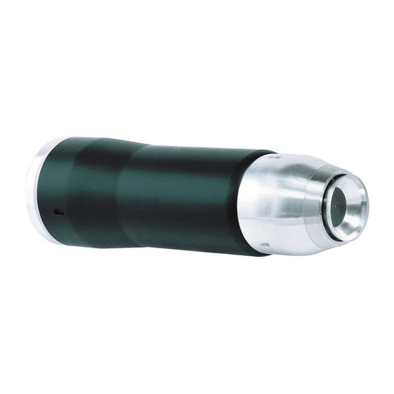
Related Manuals for SAMES KREMLIN PPH 308


Summary of Contents for SAMES KREMLIN PPH 308
- Page 1 User manual PPH 308 with high voltage cable for solvent-based paints SAMES KREMLIN SAS - 13, Chemin de Malacher - 38240 MEYLAN - FRANCE Tel. 33 (0)4 76 41 60 60 - www.sames-kremlin.com Index revision : C - November 2017 7030...
- Page 2 SAMES KREMLIN SAS operating manuals are written in French and translated into English, German, Spanish, Italian and Portuguese. The French version is deemed the official text and SAMES KREMLIN will not be liable for the translations into other languages. Index revision : C - November 2017...
-
Page 3: Table Of Contents
PPH 308 with high voltage cable for solvent-based paints 1. Health and Safety Instructions- - - - - - - - - - - - - - - - - - - - - - - - - - - - 6 1.1. - Page 4 6. Atomizer Maintenance - - - - - - - - - - - - - - - - - - - - - - - - - - - - - - - - 33 6.1. Removing and re-installing the PPH 308 ....33 6.1.1.
- Page 5 8.5. Placebo and resistor ....... 49 8.5.1. To connect to one PPH 308 atomizer ....49 8.5.2.
-
Page 6: Health And Safety Instructions
CE 0080 P/N: * ISSeP06ATEX032X** II 2 G EEx > 350mJ (Serial no.) * ATEX PPH 308 configurations P/N PPH GNM 200A P/N 1517071 910003721 ** 'X' indicates that the safety distance specified in this manual (between the HV components of the atomizer and all grounded parts) must be observed to ensure safe operation of the equipment. -
Page 7: Precautions Foruse
This document contains information that every operator must be familiar with and understand before using the PPH 308 atomizer. This information highlights situations that could result in seri- ous damage and indicates the precautions that should be taken to avoid them. - Page 8 The electrostatic spraying device must be regularly serviced in accordance with the indications and instructions given by SAMES KREMLIN. The equipment must be cleaned either in authorized areas equipped with a mechanical ventilation system, or using cleaning fluids with a flash point at least 5°C higher than the ambient temperature.
- Page 9 WARNING : The use of extra high voltage power increases the risk of sparks. SAMES KREMLIN atomizers and high-voltage electrostatic generators are designed to minimise this risk. Although the HV electrode is the only accessible part, a safety distance of X mm (see table below) must be maintained between the HV parts of the atomizer and all grounded parts.
-
Page 10: Installation Rules
system must be verified once a week. A warning sign must be placed in full view near the spraying area. Excessive turbine speed can result in serious damage to the turbine and loss of connection between the bell cup and turbine, presenting a risk to persons and equipment. Do not exceed the maximum operating speed (see §... - Page 11 PPH 308 for low resistivity solvent-based paints ρ > 0.5 MΩ.cm ρ > 0.5 MΩ.cm : L = 5 m Int.Dia.: 5 mm S: rinsing product Note: L Distance at which A: air intake grounding of paint, solvent and 1: product intake 1...
-
Page 12: Important Recommendations
5 µm diameter reaching the bearing. WARNING : The warranty does not cover damage caused by foreign matter (paint, solvent or other foreign matter) entering the air circuits of atomizer PPH 308. 1.5.2. Product quality The paint must be filtered to prevent any damage to the atomizer. -
Page 13: Locking
O-rings in order to prevent swelling or chemical corrosion. Correct operation of the PPH 308 is only guaranteed if it is used with seals whose dimensions and materials comply with those specified in the manual. -
Page 14: Ventilation
1.5.10. Ventilation Do not start painting with the PPH 308 until the spraying booth ventilation system is operating. If the ventilation is cut, toxic substances such as organic solvents or ozone may remain in the spraying booth, resulting in a risk of fire, poisoning or irritation. -
Page 15: Noise Level
The weighted equivalent continuous sound pressure level is 59.7 dB(A). Measurement conditions: The apparatus was operated to maximum capacity and the measurements taken in the paint test booth (sealed booth with glass panels) in the SAMES KREMLIN R&D laboratory in Meylan, France. Measurement method: The weighted equivalent sound pressure level of 59.7 db(A) is an Leq (equivalent sound... -
Page 16: Warranty
• contamination of air circuits by fluids or substances other than air. The SAMES KREMLIN PPH 308 atomizer is covered by a one-year warranty for use in two 8- hour shifts per day under normal operating conditions. -
Page 17: Description
The PPH 308 atomizer is used in automatic mode for the electrostatic spraying solvent liquid paints. The PPH 308 is a complete atomizer with built-in painting and rinsing assemblies. It is fitted with an air-cushioned magnetic air bearing turbine capable of reaching a rotation speed of 45,000 rpm. -
Page 18: Dual-Channel Air/Solvent Microvalve Unit (1 Pv Block)
The injector holder is permanently secured to the body of the PPH 308. It is fitted with an injector whose restrictor can be changed according to the pressure drop required for the paint spraying equipment and product used. -
Page 19: Magnetic Bell Cup" Type Magnetic Air Bearing Turbine
2.4. “Magnetic bell cup” type magnetic air bearing turbine see RT Nr 6350 The bell cup is rotated by means of a pneumatic motor. Paint is sprayed due to the centrifugal forces generated by rotation of the bell cup. The higher the rotational speed, the smaller the particles that are sprayed. -
Page 20: Technical Characteristics
3. Technical characteristics 3.1. Dimensions (mm) Index revision : C - November 2017 7030... -
Page 21: Operating Characteristics
RT Nr 6350 * Resistivity values measured with Resistivohmeter AP 1000 (SAMES P/N: 910005790). For lower values, contact SAMES KREMLIN. For values greater than 6 MΩ.cm, you are advised to use the PPH 308 with integrated high voltage unit. ** m values given for a temperature of 20 °C at 1013 mbar atmospheric pressure. -
Page 22: Operating Principle
3.3. Operating principle 3.3.1. Turbine see RT Nr 6350 This turbine has no mechanical shaft and is kept aligned simply by the polarity difference between the bearing magnets. This system also completely eliminates friction. The bearing air, which is uniformly distributed across the stator surface generates an air cushion, separating rotor and stator. -
Page 23: Turbine Rotation Speed
The microphone is linked to a SAMES KREMLIN frequency/voltage control to convert the analogue frequency signal into an analogue level signal (0 - 10 V) or digital signal (pulse). Please contact SAMES KREMLIN for the appropriate part number for use with your set-up. Index revision : C - November 2017... -
Page 24: Fluid Diagram Of The Various Circuits
4. Fluid Diagram of the Various Circuits 4.1. Paint flow diagram For use of the rinsing circuit (generally used to change colours) Paint supply - Dia. 5 x 8 PTFE Dump - Dia 5 x 8 PTFE Paint supply pilot - Dia 2.7 x 4 - Polyamide Dump pilot - Dia 2.7 x 4 - Polyamide The “11”... -
Page 25: Microphone Air Diagram
4.3. Microphone air diagram The microphone air is controlled by a remote regulator. Microphone air - Dia. 4 x 6 - Polyamide Microphone return supply - Dia. 4 x 6 - Polyamide 4.4. Turbine rotation diagram Turbine rotation - Dia. 7 x 10 - Polyure- thane Turbine braking - Dia. -
Page 26: Compensation Air Diagram
4.6. Compensation air diagram OD 5/16" NYLON Compensation air - Dia. 6 x 8 - Poly- amide 25 : The compensation air prevents any contamination of the inner shaping air shroud and is controlled via a remote regulator. 4.7. Turbine exhaust diagram Turbine exhaust - Dia. -
Page 27: Colour Change And Rinsing Cycles
4.8. Colour change and rinsing cycles Example of atomizer integration Flow-rate adjustment restrictor (300 cc/min) Colours Colour change block PV41 PV41 PV11 PV11 PV32 PV32 PV31 PV31 Flow-rate adjustment restrictor (250 cc/min) Rinsing supply circuit only Seconds Air PV - Colour change block Solvent PV - Colour change block... - Page 28 Rinsing bell cup only Seconds Solvent PV - injector rinsing Air PV - injector rinsing Solvent PV- bell cup rinsing Air PV- bell cup Example of start-up cycle Option Standard Seconds Seconds Paint PV - Colour Paint PV - Colour change block change block Dump valve...
-
Page 29: Maintenance
5. Maintenance 5.1. Shut-down and start-up procedures Important recommendations Comply with the air settings given in Section 3.2. The rotor and stator become inoperable if the bearing air is cut off during rotation. The bearing air pressure must be at least 6 bar at the quick-disconnect plate. (*For hose lengths greater than 4.5 m, the correct air pressure value is determined by taking the measurement at the quick-disconnect plate). -
Page 30: Tools
5.2. Tools Part number Description Unit of sale 1308689 Outer cover removal/reassembly tool Part number Description Unit of sale 1204427 Removal tool for magnetic bell cup 65 EC 900000803 Removal tool for magnetic bell cup 50 EC 900000804 Removal tool for magnetic bell cup 35 EC Part number Description Unit of sale... - Page 31 Part number Description Unit of sale H1GMIN017 Vaseline (100 ml) H1GSYN037 Dielectric grease (100 ml) Index revision : C - November 2017 7030...
-
Page 32: Installing The Atomizer
(5/8 PTFE) must also be sheathed with a 9/12 PTFE hose. • Thread the hoses and high voltage cable through the support tube. • Secure atomizer PPH 308 to the support tube with four M 8 x 30 screws. • Screw the cover on to the atomizer. -
Page 33: Atomizer Maintenance
• Disconnect all hoses entering the Manifold block and 1 PV block (except hoses connected between the 1 PV block and Manifold block). • Loosen the 4 screws securing PPH 308 to holder. WARNING : Do not remove the clamps from the MANIFOLD block to make sure they are not lost. -
Page 34: Injector Holder
6.5. Injector holder The injector holder is secured to the body of the PPH 308 by three M3 x 10 screws. Its positioning pin ensures correct positioning. Injector holder Injector Bell cup 6.6. Injector 6.6.1. Disassembly • Switch off the machine. -
Page 35: Pv Block And Manifold Block
6.7. 1 PV Block and Manifold Block 6.7.1. Disassembly • Remove PPH 308. • Loosen the screw securing the 1 PV block onto the tie-rod. • Disconnect the hoses between 1 PV block and Manifold block. • Uncrew the tie-rod (see §... -
Page 36: High Voltage Connection
6.9. High Voltage Connection 6.9.1. Preparing the high voltage connection Cable-securing Supporting High voltage Split End fitting adapter Clamp Protective hose cable cone WARNING : Ensure that insulation is not damaged. Any scratch or start of a cut on the surface of the insulating material will result in breakdown of the high voltage cable. -
Page 37: Assembling / Disassembling The Internal Resistor In The Placebo
• Step 4: Insert the end fitting into the high voltage cable and screw on manually, then with a 6 mm open-ended spanner. Tighten fully. • Step 5: Lubrication • Coat the high voltage cable end fitting with a layer of dielectric Step 5 lubricant. -
Page 38: Installation On Atomizer
6.9.3. Installation on atomizer • Step 1: Insert placebo assembly into PPH 308 sheath (see § 8.1 page 43 item 10). • Step 2: Screw in securing screw (see § 8.1 page 43 item 12), but do not fully tighten. -
Page 39: Cleaning Procedures
These films are conductive and can short-circuit the high voltage. SAMES KREMLIN forbids the use of adhesives on the insulating parts of the atomizers. The glue of the adhesives is conductive and thus can short-circuit the high voltage. -
Page 40: Procedure A
7.1. Procedure A WARNING : Switch off the turbine. The bearing air and shaping air remains pressurised in order to prevent solvent passing between the bell cup and shaping air shroud. • Clean the outer cover and outside of the bell cup with a clean cloth, dampened with solvent. -
Page 41: Procedure B
7.2. Procedure B WARNING : Stop the turbine and cut off the shaping air 7.2.1. Bell cup • Remove the bell cup using the specific tool. • Leave the bell cup soaking in solvent for one hour then clean with a clean cloth and soft brush. -
Page 42: Outer Cover
7.2.2. Outer cover • Remove the shaping air assembly Outer cover O-ring Shaping air shroud • Step 2: Leave the outer cover to soak in solvent for one hour then clean the outer and inner surface with a cloth soaked in solvent. -
Page 43: Spare Parts List
8. Spare Parts List 8.1. Single-circuit PPH 308 for solvent-based paints of resistivity 0.5 < ρ ≤ 6 MΩ.cm Bell cup and shaping air assembly not included. Index revision : C - November 2017 7030... - Page 44 910005997 1 PV block (see § 8.2 page 45). 1405874 Tie rod for 2 PV block 1203616 PPH 308 Tube holder - D:63 1204441 Nut for tube 910006552 Sealing screwed union for 12/8-hose 910006017 Sealing screwed union for 10/6-hose Not shown...
-
Page 45: Pv Block
8.2. 1 PV Block Unit First Item Part number Description Wear priority sale 910005997 1 PV Block F6RPUK317 Male straight union 1/4 BSP for 4/6 hose F6RLUS268 Male union X9NVCB181 Nylon screw C M 5 x 10 1507375 Microvalve (see RT Nr 6021) F6RPUQ062 Male union, 4 1/8”... -
Page 46: Manifold Block
8.3. MANIFOLD Block Unit First Item Part number Description Wear priority sale 910003632 Manifold block 1405931 Slotted screw, C M3 x 50 (brass) 1402691 Cover positioning device J3STKL078 Chemically-inert O-ring 1507375 Microvalve (see RT Nr 6021) J3STKL002 Chemically-inert O-ring J3STKL039 Chemically-inert O-ring J3STKL026 Chemically-inert O-ring... - Page 47 Unit of First Item Part number Description Wear sale priority 449707 Spacer J2FTCF051 O-ring F6RPUQ062 Male union 910001739 1/4 Rack coupling for 5/8 hose F6RXZG081 Stainless steel clamp and seal F6RXZG082 Stainless steel clamp and seal F6RXZG083 Stainless steel clamp and seal F6RXZG084 Stainless steel clamp and seal Index revision : C - November 2017...
-
Page 48: Injector / Injector Holder Assembly
8.4. Injector / Injector holder assembly Unit First Item Part number Description Wear priority sale 910001130 Injector / Injector holder assembly 738354 Injector holder X4FVSY067 Stainless steel screw C M 3 x 10 J3STKL014 O-ring - chemically inert 738635 Injector Dia: 1,8 J3STKL005 O-ring - chemically inert Index revision : C - November 2017... -
Page 49: Placebo And Resistor
8.5. Placebo and resistor 8.5.1. To connect to one PPH 308 atomizer If the resistor requires replacement, use the special tool (P/N 900002675) to screw the new resistor into the placebo. Unit of First Item Part number Description Wear sale... -
Page 50: To Connect Two Pph 308 Atomizers To A Single Hvu
8.5.2. To connect two PPH 308 atomizers to a single HVU (optional) Unit of First Item Part number Description Wear sale priority 910003563 Placebo and resistor Protective hose for HV cable, D:10/12 4.25 U1CBBR057 clear polyamide 4.25 E2DAVD101 High voltage cable (100kV) -
Page 51: Grounding Kit
8.6. Grounding kit Unit of First Item Part number Description Wear sale priority 910003399 Grounding kit X7CVHA226 Bolt, H M6 x 20 (brass) X7CEHU006 Nut, H M 6 (brass) F6RXGQ056 Bulkhead union F6RXZX061 Stainless steel sheath Index revision : C - November 2017 7030... -
Page 52: Turbine, Injector And Restrictor Seals
8.7. Turbine, injector and restrictor seals Injector Restrictor Part number Restrictor Number of grooves Colour 640400 D: 0.8 mm Black 640401 D: 0.9 mm Black 640402 D: 1.0 mm Black 640403 D: 1.2 mm White 640456 D: 1.5 mm White 640464 D: 3.0 mm White...
Need help?
Do you have a question about the PPH 308 and is the answer not in the manual?
Questions and answers