Table of Contents
Advertisement
Quick Links
From February 1st, 2017 SAMES Technologies SAS becomes SAMES KREMLIN SAS
A partir du 1/02/17, SAMES Technologies SAS devient SAMES KREMLIN SAS
User manual
PPH 707 CHEM ICWB M TI
Atomizer
SAS SAMES Technologies. 13 Chemin de Malacher -
Inovallée - CS 70086 - 38243 Meylan Cedex
Tel. 33 (0)4 76 41 60 60 - Fax. 33 (0)4 76 41 60 90 - www.sames.com
Index revision : A
1
7116
Advertisement
Table of Contents

Subscribe to Our Youtube Channel
Related Manuals for SAMES KREMLIN PPH 707 CHEM ICWB M TI


Summary of Contents for SAMES KREMLIN PPH 707 CHEM ICWB M TI
- Page 1 From February 1st, 2017 SAMES Technologies SAS becomes SAMES KREMLIN SAS A partir du 1/02/17, SAMES Technologies SAS devient SAMES KREMLIN SAS User manual PPH 707 CHEM ICWB M TI Atomizer SAS SAMES Technologies. 13 Chemin de Malacher - Inovallée - CS 70086 - 38243 Meylan Cedex Tel.
- Page 2 All communication or reproduction of this document, in any form whatsoever and all use or communication of its contents are forbidden without express written authorisation from SAMES Technologies. The descriptions and characteristics mentioned in this document are subject to change without prior notice.
-
Page 3: Table Of Contents
PPH 707 CHEM ICWB M TI Atomizer 1. Health and Safety Instructions - - - - - - - - - - - - - - - - - - - - - - - - - - - - 5 1.1. - Page 4 7.5. EC 50 Hi-TE shaping air assembly and bellcup specific to the PPH 707 CHEM ICWB M TI ......53...
-
Page 5: Pph 707 Chem Icwb M Ti
1.1. Configuration of certified equipment These user manuals define the configuration of certified equipment. 1.2. Marking on atomizer SAMES Meylan FRANCE PPH 707 CHEM ICWB M TI CE 0080 II 2 G EEx > 350mJ ISSeP06ATEX032X** P/N : * (Serial no.) -
Page 6: Precautions For Use
WARNING : Before any use of the PPH 707 CHEM ICWB M TI equipment, check that all operators: • have previously be trained by the compagny Sames Technologies, or by their distributors regis- tered by them for this purpose. - Page 7 WARNING : This equipment must only be used in spraying areas in compliance with standards EN 50176, EN 50177, EN 50223, or under equivalent ventilation conditions. To reduce health, fire and explo- sion risks, this equipment must only be used in well ventilated areas. The efficiency of the ventilation system must be verified on a daily basis.
- Page 8 WARNING : The use of very high voltage increases the risk of sparks. SAMES Technologies atomizers and high-voltage electrostatic generators are designed to minimise this risk. Although the HV electrode is the only accessible part, a safety distance of X mm (see table below) must be observed between the HV parts of the atomizer and all grounded parts.
- Page 9 A warning sign must be placed in full view near the spraying area. Excessive turbine speed can result in serious damage to the turbine and loss of connection between the bell cup and turbine, presenting a risk to persons and equipment. The maximum operating speed spec- ified in this manual must not be exceeded (see §...
-
Page 10: Installation Rules
Low voltage connection High voltage unit UHT 287 EEx e High voltage cable connecting insulating table to UHT 287 and to PPH 707 CHEM ICWB M TI Supplies of coating products and rinsing products insulated to the ground potential Dump return line insulated to the ground potential... -
Page 11: Important Recommendations
1.5. Important Recommendations 1.5.1. Compressed air quality The air must be filtered to a level that will guarantee a long life time and prevent any pollution during covering. The filter must be installed as close to the installation as possible. The filter cartridges must be changed regularly to ensure that the air is clean. -
Page 12: Shaping Air
The correct operation of atomizer PPH 707 CHEM ICWB M TI is only guaranteed if used with seals of sizes and materials in com- pliance with those specified in this manual. -
Page 13: Safety Devices
1.5.12. Safety devices When implementing atomizer PPH 707 CHEM ICWB M TI, it is important to provide for safety devices allowing immediate cutoff of coating product, solvent, air and HV power supplies in the event of a problem. • Detection of control system faults. -
Page 14: Guarantee
• pollution of air circuits by fluids or substances other than air. The SAMES Technologies atomizer PPH 707 CHEM ICWB M TI is covered by a one-year guarantee for use in two 8-hour shifts under normal operating conditions. -
Page 15: Description
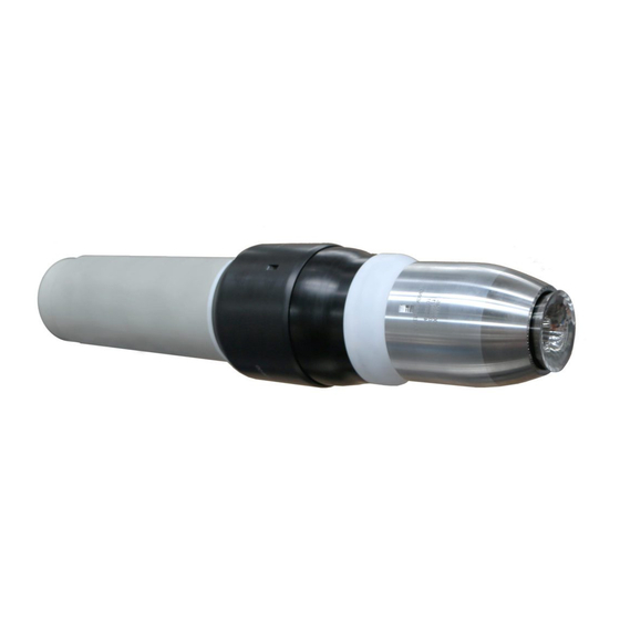
2. Description 2.1. General Atomizer PPH 707 CHEM ICWB M TI is a high-performance atomizer with rotating bell cup. It incorpo- rates the advantages of previous generations, with added power. It is designed for high spray rates. The PPH 707 CHEM ICWB M was developed to resist the aggressive or corrosive chemicals. The choice of materials was made for a resistance strengthened to the organic solvents, to the strong acids and to the powerful oxidizers, on the other hand it is not adapted to spray the strong bases. -
Page 16: Function Of The Parts
Allows quick installation and removal of the atomizer during production. It secures the body on the support tube. Supply with high voltage the PPH 707 CHEM ICWB M TI High voltage connection atomizer from the external high voltage unit. -
Page 17: Technical Characteristics
3. Technical characteristics 3.1. Dimensions (mm) Index revision : A 7116... -
Page 18: Operating Characteristics
3.2. Operating characteristics Weight Atomizer without cable or hose 9.6 kg Voltage Maximum operating voltage 70 kV 500 μA Maximum operating current Speed Recommended rotation speed 15 to 80 Krpm. Product 20 to 1000 cm /mn max. (depending Flow rate on product) Normal supply pressure 6 to 8 bar... -
Page 19: Operating Principle
3.3. Operating principle 3.3.1. Turbine see RT Nr 6354 The turbine is equipped with an air bearing that separates the transmission shaft and drive vane from the main body of the turbine. This eliminates friction between the various components, ensuring long component life and allowing high rotation speeds. -
Page 20: Fluid Diagram
4. Fluid diagram Air jupe 3 Ø6/8 Prise de pression air de jupe Ø2.7/4 Air jupe 1 Ø6/8 Air jupe 2 Ø6/8 Air palier Ø4/6 Freinage turbine Ø4/6 Rotation turbine Ø6/8 Rotation turbine Ø6/8 Air micro Ø4/6 Purge circuit 1 Ø4/6teflon gainé... - Page 21 Note: Blue colored hoses are used for the various types of air supply. Non-colored hoses are used for products. WARNING : 11,12,41,and 42 (4/6 PTFE) hoses and 31-hose (3/6 PTFE) will have to be sheathe with 7/10 PTFE hoses. The overall length of the sheath must be approximately 5 cm lower than the length of the hoses.
-
Page 22: Startup
5. Startup 5.1. Tools Unit of Part Number Description sale 900004492 Installation/removal tool for outer cover and rear nut Unit of Part Number Description sale 900000803 Removal tool for EC 50 magnetic bell cup Unit of Part Number Description sale 1301832 Removal tool for nanovalve 1403498... - Page 23 Unit of Part Number Description sale 1303689 Removal tool for microvalve 1403478 Automatic tightening tool for microvalve Unit of Part Number Description sale 1313955 Installation tool for fittings Unit of Part Number Description sale 900002665 Trapezoidal tool for clipped fittings Unit of Part Number Description...
- Page 24 Additional tools and accessories required: The tools listed below should be available for product installation and maintenance operations. • Hose cutter (P/N W3SCTU002) • Screwdriver (small and medium) • Allen wrench (3.4 mm) • Torque wrench • Fine brush • Flat wrenches (9 and 12 mm) •...
-
Page 25: Installation
5.2. Installation • Step 1: Loosen the two fastening screws and Locking withdraw the quick disconnect plate from the screw rear support. • Step 2: Pass the hose bundle (air and product hoses) through the support tube. Pass one by one the hoses through the quick disconnect plate by respecting their location. -
Page 26: Shutdown And Startup Procedures
5.3. Shutdown and startup procedures Important recommendations: Comply with the air settings given in Section 3.2. The bearing air pressure must be at least 5.5 bar at the quick-disconnect plate. Check that the speed regulating module transmits a signal. 5.3.1. Shutdown procedure Important steps be observed: Step 1 Step 2... -
Page 27: Maintenance
6. Maintenance 6.1. Summary table of maintenance operations Procedure Description Preventive Corrective Duration Frequency Cleaning of atomizer exterior, outer 5 mn 8 hours cover, and bell cup exterior Cleaning of bell cup 2 mn 40 hours Cleaning of outer cover 8 mn 40 hours Cleaning of injector exterior... -
Page 28: Preventive Maintenance
6.2. Preventive maintenance These maintenance operations can be performed online. Always refer to the health and safety instructions before carrying out any work (see § 1.4 page WARNING : Considering the spraying of aggressive chemicals and or corrosive, it is imperative to arm itself with personal protective equipments adapted to these products (gloves, visor / glasses, chemical protective clothes, shoes). - Page 29 Grooves on the outer cover Outer cover Bell cup • Clean the outer cover and the bell cup exterior with a clean cloth. • Check that the grooves on the outer cover are clean. • Dry carefully. Index revision : A 7116...
-
Page 30: Procedure B1: Magnetic Bell Cup
6.2.2. Procedure B1: Magnetic bell cup WARNING : All bell cup maintenance or handling operations must be performed with extreme care, since the bell cup is balanced. WARNING : Stop the turbine and cut off the shaping air. The bearing air remains pressurized. •... -
Page 31: Procedure B2: Shaping Air Assembly
6.2.3. Procedure B2: Shaping air assembly • The bell cup has been previously removed. • Begin to loosen the outer cover with tool P/N 900004396, then continue manually. • Remove the outer cover, then remove the inner shaping air shroud. •... -
Page 32: Procedure B3: Injector Exterior
6.2.4. Procedure B3: Injector exterior Proceed with the bell cup and shaping air shroud assembly previously removed. • Use a brush slightly soaked in a rinsing liquid to clean the injector exterior. • Dry carefully with a clean, dry, non-fluffy cloth. Index revision : A 7116... -
Page 33: Procedure C1: Turbine
6.2.5. Procedure C1: Turbine • Proceed with the bell cup and shaping air assembly previously removed. • Loosen the three turbine fastening screws. 3 captive screws • Clean the turbine interior with a cylindrical brush. • Clean the turbine exterior with a soft, non-fluffy cloth. -
Page 34: Procedure C2: Injector / Injector Holder
6.2.6. Procedure C2: Injector / Injector holder • Proceed with the bell cup, shaping air assembly and turbine previously removed. • Use a 9-mm flat wrench to loosen the injector/ diffuser assembly. Withdraw the injector from the diffuser by pushing it carefully. WARNING : All operations on the injector must be performed carefully. -
Page 35: Corrective Maintenance
6.3. Corrective maintenance The following operations are preferably performed in a workshop. 6.3.1. Procedure D1: Body installation/removal • Remove the body: Unscrew the PPH nut then pull the body assembly along the axis. • Reinstall the body: Proceed in reverse order. 6.3.2. -
Page 36: Procedure D4: Replacement Of Nanovalves
6.3.4. Procedure D4: Replacement of nanovalves • Remove the nanovalves: see RT Nr 6258 for the operations listed below. Remove the nanovalves using tool P/N 1301832. Nanovalves Check their condition, clean them, and replace if necessary. 6.3.5. Procedure D5: Replacement of microvalves with bellow •... -
Page 37: Procedure E1: Hose Replacement
6.3.7. Procedure E1: Hose replacement • Hose replacement: It is not necessary to separate the quick-dis- connect plate from the rear support in order to For 6/8 dia. fit- For 2.7/4 and 4/6 access the fittings or hoses or remove the tings dia. -
Page 38: Procedure E2: Replacement Of Fittings
6.3.8. Procedure E2: Replacement of fittings • Remove the air fitting from the hose: Hold the hose using tool P/N 1313955, insert the hose in the orifice corresponding to the hose diameter, and loosen using a flat wrench with diameter corresponding to the fitting diameter. •... -
Page 39: Procedure E3: Replacement Of High Voltage Connection
6.3.9. Procedure E3: Replacement of high voltage connection • Remove the body. • Withdraw the high voltage connection, loosen the fastening screw. High voltage connection • Then pull the high voltage connection. • Position the new high voltage connection after previously coating the high voltage well with dielec- tric grease. - Page 40 6.3.9.1. Preparation of the high voltage connection Holder Sleeve HV cable Split Terminal Grip cone Resistance Ground Plug Banana plug WARNING : Ensure not to damage the insulating jacket. The smallest nick or mark on the insulating jacket will cause the cable breakdown. •...
- Page 41 • Step 4: Insert the end piece in the high voltage cable, screw it manually then using a 6 mm open end wrench, tighten it until it stops. Step 4 60 - 70 mm The split cone must be positionned between 60 and 70 mm from the sleeve-terminal end assembly.
-
Page 42: Procedure E4: Replacement Of Quick-Disconnect Plate
6.3.10. Procedure E4: Replacement of quick-disconnect plate • Loosen the two fastening screws (M5x15) and withdraw the quick-disconnect plate. • Remove the fittings from each hose (see § 6.3.8 page • Position the new quick-disconnect plate and the hoses, then reinstall the fittings (see §... -
Page 43: Spare Parts List
7. Spare parts list WARNING : In order to guarantee an optimum assembly, the spare parts must be stored at a temperature close to their temperature of use. If not, a sufficient time must be observed before the installation, so that all the elements are assembled at the same temperature. - Page 44 Description for spare part sale 910021384 PPH 707 CHEM ICWB M TI 900002645 Valve cover PPH 707 CHEM ICWB M TI body assem- 910021385SAV (see § 7.1 page High voltage connection 910021895 (see § 7.3 page Quick disconnect plate assembly 910003409 (see §...
-
Page 45: Pph 707 Chem Icwb M Ti Body Assembly
7.1. PPH 707 CHEM ICWB M TI body assembly Maintenance Unit level Item Part Number Description for spare sale part (*) PPH 707 CHEM ICWB M TI body 910021385SAV assembly Equipped body 910021386SAV (see § 7.1.1 page Injector / Injector holder assembly 910021361 (see §... -
Page 46: Pph 707 Chem Icwb M Ti Body
7.1.1. PPH 707 CHEM ICWB M TI body Maintenance Unit level Item Part Number Description for spare sale part (*) 910021386SAV Equipped body Microvalve with bellow, orange indicator, 910010850 chemically inert o-rings (see RT Nr 6422) Nanovalve, orange indicator, chemically... - Page 47 7.1.1.1. O-ring kit (high speed turbine side) Maintenance Unit of level Item Part Number Description sale for spare part 910003415 O-ring kit (high-speed turbine side) J3STKL082 O-ring (chemically inert) J3STKL046 O-ring (chemically inert) 160000028 Flat seal J3STKL035 O-ring (chemically inert) J3STKL002 O-ring (chemically inert) Level 1: Standard preventive maintenance...
- Page 48 7.1.1.2. O-ring kit (quick disconnect plate side) Maintenance Unit of level Item Part Number Description sale for spare part 910003416 O-ring kit (quick disconnect plate side) J3STKL121 O-ring (chemically inert) J3STKL078 O-ring (chemically inert) 160000027 Flat seal J3STKL094 O-ring (chemically inert) Level 1: Standard preventive maintenance Level 2: Corrective maintenance Level 3: Exceptional maintenance...
-
Page 49: Injector / Injector Holder Assembly
7.1.2. Injector / injector holder assembly Maintenance Unit of level Item Part Number Description sale for spare part 910021361 Injector / injector holder assembly 900014212 Diffuser J3STKL069 O-ring (chemically inert) 900014211 Slot Injector (dia.:0.9) 900010925 Flat seal - PEHD 900014210 High-speed turbine injector holder X4FVSY066 C M3x 8 screw (stainless steel) -
Page 50: Quick-Disconnect Plate Assembly
7.2. Quick-disconnect plate assembly Maintenance Unit of level Item Part Number Description sale for spare part 910003409 Quick disconnect plate assembly 900003914 High voltage unit locking screw 910002946 2.7/4 air fitting 910002948 6/8 air fitting 910002947 4/6 air fitting 910003413 3/6 product fitting X9SVCB183 C M 5 x 15 screw (fiber-glass nylon) -
Page 51: High Voltage Connection
7.3. High voltage connection Maintenance Unit level Item Part Number Description for spare part sale 910021895 High voltage connection J2FENV445 O-ring - FEP viton 900014511 Ground plug 110000548 Banana plug 910022101 Resistance assembly E4CSHT181 Cable terminal end 1411690 Sleeve, 100kV cable end 1411689 Split cone 1315058... -
Page 52: Pph 707 Chem Icwb M Ti Support Assembly
7.4. PPH 707 CHEM ICWB M TI support assembly Maintenance Unit level Item Part Number Description for spare sale part (*) PPH 707 CHEM ICWB M TI support 910020317 assembly X2BVHA291 H M8 x 60 zinc plated screw X9SVCB186 C M5x 20 screw (fiber-glass nylon) -
Page 53: Ec 50 Hi-Te Shaping Air Assembly And Bellcup Specific To The Pph 707 Chem Icwb M Ti
7.5. EC 50 Hi-TE shaping air assembly and bellcup specific to the PPH 707 CHEM ICWB M TI Restrictor housing Maintenance Unit level Item Part Number Description for spare sale part (*) 910021387 EC 50 Hi-TE shaping air assembly J2FENV622...
Need help?
Do you have a question about the PPH 707 CHEM ICWB M TI and is the answer not in the manual?
Questions and answers