Table of Contents
Advertisement
Quick Links
Installation AND MAINTENANCE INSTRUCTIONS
Series
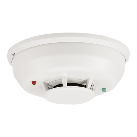
Photoelectric Smoke Detector
2-Wire:
2WTR-B (Form C Relay), 2WTA-B (Sounder)
4-Wire:
4WTR-B (Form C Relay), 4WTA-B (Sounder)
4WTAR-B (Form C Relay, Sounder), 4WITAR-B (Isolated Thermal, Form C Relay, Sounder)
ELECTRICAL SPECIFICATIONS
System Voltage –Nominal:
Min.:
Max.:
Max. Ripple Voltage:
Avg. Standby Current:
Peak Standby Current:
Max. Alarm Current
4WTA-B, 4WTR-B:
4WTAR-B, 4WITAR-B:
2WTR-B:
2WTA-B:
Alarm Contact Ratings:
Form C Contact Ratings:
Audible Signal
(temp-3 tone):
Remote Annunciator Output:
EOL Relay:
Reset Time (min):
Max. Start-up Capacitance:
Max. Initial Start-up Time:
AlarmVerification** Start-up Time:
* Direct Power (Non-reverse Polarity): 130 mA limited by panel.
Reverse Polarity Power: 30 mA for the 2WTA-B in alarm; 12 mA for all other 2WTA-B units on the loop. Add 25 mA for the RRS-MOD reversing relay alarm current.
** Assumes the panel's alarm verification reset time is 10 seconds or less. Should the alarm verification reset exceed 10 seconds, use the maximum initial start-up time.
PHYSICAL SPECIFICATIONS
Heat Sensor:
Freeze Trouble:
Operating Temperature Range:
Operating Humidity Range:
Storage Temperature Range:
Diameter (including base):
Height (including base):
Weight:
BEFORE INSTALLING
Please read thoroughly System Sensor's Applications Guide for System Smoke
Detectors (SPAG91), which provides detailed information on detector spacing,
placement, zoning, wiring, and special applications. This is available online
from System Sensor's web site: www.systemsensor.com.
NOTICE: This manual shall be left with the owner/user of this equipment.
IMPORTANT: This detector must be tested and maintained regularly follow-
ing National Fire Protection Association (NFPA) 72 National Fire Alarm Code
requirements. At a minimum, cleaning should be performed annually.
GENERAL DESCRIPTION
Models 2WTR-B and 2WTA-B are 2-wire photoelectric smoke detectors; models
4WTR-B, 4WTA-B, 4WTAR-B, and 4WITAR-B are 4-wire photoelectric smoke
detectors. All models incorporate a state-of-the-art optical sensing chamber
and an advanced microprocessor. The microprocessor allows the detector to
automatically adjust its sensitivity back to the factory setting when it becomes
more sensitive due to contaminants settling in its chamber. In order for this
feature to work properly, the chamber must never be opened while power is
applied to the smoke detector. This includes cleaning, maintenance or screen
replacement. All models also feature a restorable, built-in, fixed temperature
(135°F) thermal detector and are also capable of sensing a freeze condition if
the temperature is below 41°F.
Models 2WTA-B, 4WTA-B, 4WTAR-B, and 4WITAR-B contain a piezoelectric
horn which generates the ANSI S3.41 temporal pattern in an alarm condition.
2-wire
4-wire
12/24
12/24
V
(Non-polarized for 2WTR-B and 4WTR-B)
8.5
10
V
35
35
V
30
30
% peak to peak of applied voltage
50
50
µA average
100
—
µA
—
35
mA
—
50
mA
130
—
mA panel must limit current
130*
—
0.5
A @ 30 V AC/DC
2
2
A @ 30 V AC/DC
85
85
dBA min. in alarm or supply polarity reversed (Sounder units only)
7
—
mA maximum
—
12/24
EOLR-1
0.3
0.3
seconds
0.1
—
µF
45
15
seconds
15
15
seconds
135°F (57.2°C)
41°F (5°C)
32 to 100°F (0 to 37.8°C)
0 to 95% RH non-condensing
–4 to 158°F (–20 to 70°C)
5.3 inches
2.0 inches
7.1 oz.
3825 Ohio Avenue, St. Charles, Illinois 60174
All detectors on a zone will sound when the power supply to them is reversed.
The RRS-MOD can be used for the power supply reversal function. The RRS-
MOD also enables all the detectors' sounders on a zone to be synchronized
and allows the zone to be silenced from the panel by entering the alarm si-
lence key at the keypad.
The detector that initiated the alarm condition will have its red LED and Form
C relays (if applicable) latched until reset by panel.
The model 4WITAR-B photoelectronic smoke sensor is isolated from the fixed-
temperature heat sensor, providing a self-resetting, local audible smoke alarm
that does not alarm at the panel. Only the fixed-temperature heat sensor will
cause the 4WITAR-B to initiate an alarm at the panel and the relay to change
its state.
NOTE: In order for all i3 sounder detectors on a loop to sound when the panel
alarms, the supply voltage polarity must be reversed. A reversing relay, System
Sensor model number RRS-MOD, must be used. The RRS-MOD is designed
to allow all i3 Series detectors in the same loop to sound when one of the
detectors goes into alarm. In addition, the RRS-MOD will synchronize all of
the i3 Series sounder smoke detectors on the loop. Some panels may require
the use of programmable outputs. Refer to System Sensor literature for further
information on the RRS-MOD.
3
All i
Series detectors are designed to provide open area protection. Two-wire models
must be used with compatible UL Listed panels only.
1
1-800-SENSOR2, FAX: 630-377-6495
www.systemsensor.com
I56-2170-010
02-20
Advertisement
Table of Contents

Related Manuals for System Sensor 2WTR-B


Summary of Contents for System Sensor 2WTR-B
- Page 1 Series sounder smoke detectors on the loop. Some panels may require (135°F) thermal detector and are also capable of sensing a freeze condition if the use of programmable outputs. Refer to System Sensor literature for further the temperature is below 41°F.
- Page 2 Series detector is supplied with a mounting base that can be ceiling- or at www.systemsensor.com. wall-mounted: NOTE: Models 2WTR-B and 2WTA-B are not to be installed on initiating cir- To a single gang box, or cuits containing other makes/models of smoke detectors.
- Page 3 (2W-B, 2WT-B, or system undergoing maintenance to prevent any unwanted alarms. 2WTA-B, or 2WTR-B) on Style D IDC’s is to use a 2W-MOD2 module. Refer to Ensure proper wiring and power is applied. After power up, allow 80 seconds the 2W-MOD2 installation manual, document D500-46-00, for Style D wiring for the detector to stabilize before testing.
- Page 4 Please refer to insert for the Limitations of Fire Alarm Systems THREE-YEAR LIMITED WARRANTY System Sensor warrants its enclosed product to be free from defects in materials and TX 79936, USA. Please include a note describing the malfunction and suspected cause workmanship under normal use and service for a period of three years from date of of failure.
Need help?
Do you have a question about the 2WTR-B and is the answer not in the manual?
Questions and answers