Table of Contents
Advertisement
Available languages
Available languages
Quick Links
104 mm
B501RF
62 mm
+
132 g
48 g
(66 g)
Figure 1: B501RF Mounting
≤ M4
Figure 2: Attaching Sensor Head to Base
LINE UP MARK ON
SENSOR HEAD
WITH BULGE ON
BASE AND TURN
CLOCKWISE
Figure 3a: Activation of Tamper Resist Feature
PLASTIC LEVER
Figure 3b: Removing Sensor Head From Base
USE A SMALL-BLADED SCREWDRIVER TO PUSH
PLASTIC IN THE DIRECTION OF THE ARROW
D200-301-00
WIRELESS OPTICAL SMOKE SENSOR
INSTALLATION AND MAINTENANCE INSTRUCTIONS
32 mm
=
246 g
50-60 mm
BULGE
MARK ON
SENSOR HEAD
BREAK TAB AT DOTTED LINE BY
TWISTING TOWARDS CENTRE OF
BASE
Pittway Tecnologica S.r.l. Via Caboto 19/3, 34147 TRIESTE, Italy
22051E-RF
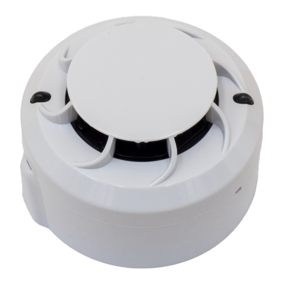
DESCRIPTION
The 22051E-RF radio sensor is a battery operated RF device designed for
use with the M200G-RF radio gateway. It contains a wireless transceiver
40°C
and runs on an addressable fire system (using a compatible proprietary
communication protocol).
-30°C
It is an optical smoke sensor.
The sensor plugs into the B501RF wireless sensor base.
This device conforms to EN54-25 and EN54-7. It complies with the
requirements of 2014/53/EU for conformance with the RED directive.
SPECIFICATIONS
Supply Voltage:
Standby Current:
Red LED Current Max: 4mA
Re-sync time:
Batteries:
Battery Life:
Radio Frequency:
RF output power:
Range:
Relative Humidity:
INSTALLATION
This equipment and any associated work must be installed in accordance
with all relevant codes and regulations.
Figure 1 details the installation of the B501RF base.
Spacing between radio system devices must be a minimum of 1m
Figure 2 details attaching the sensor head to the base.
Anti-Tamper Features
The base includes a feature that, when activated, prevents removal of the
sensor from the base without the use of a tool. See Figures 3a and 3b for
details on this.
Head Removal Warning - An alert message is signalled to the CIE via the
Gateway when a head is removed from its base.
Figure 4 details the battery installation and the location of the rotary
address switches.
Batteries should only be installed at the time of commissioning
Using these battery products for long periods at temperatures below
-20°C can reduce the battery life considerably (by up to 30% or more)
Observe the battery manufacturer's precautions for use and
SETTING THE ADDRESS
Set the loop address by turning the two rotary decade switches on the
underside of the sensor (see figure 4), using a screwdriver to rotate the
wheels to the desired address. The device will take one sensor address
on the loop. Select a number between 01 and 159 (Note: The number of
addresses available will be dependent on panel capability, check the panel
documentation for information on this).
PROGRAMMING
To load network parameters into the RF sensor, it is necessary to link the RF
gateway and the RF sensor in a configuration operation. At commissioning
time, with the RF network devices powered on, the RF gateway will
connect and programme them with network information as necessary. The
RF sensor then synchronises with its other associated devices as the RF
mesh network is created by the gateway. (For further information, see the
Radio Programming and Commissioning Manual - ref. D200-306-00.)
NOTE: Do not run more than one interface at a time to commission
devices in an area.
I 56- 4224- 002
3.3 V Direct Current max.
@ 3V: 120 µA (typical in normal operating mode)
35s (max time to normal RF communication from
device power on)
4 X Duracell Ultra123
4 years @ 25
C
o
865-870 MHz;
14dBm (max)
500m (typ. in free air)
10% to 93% (non-condensing)
Important
Warning
requirements for disposal
E N G L I S H
I56-4224-002
Advertisement
Table of Contents

Related Manuals for System Sensor 22051E-RF


Summary of Contents for System Sensor 22051E-RF
- Page 1 INSTALLATION AND MAINTENANCE INSTRUCTIONS DESCRIPTION 104 mm The 22051E-RF radio sensor is a battery operated RF device designed for use with the M200G-RF radio gateway. It contains a wireless transceiver 40°C and runs on an addressable fire system (using a compatible proprietary...
- Page 2 COVER REMOVAL TABS EU Declaration of Conformity Hereby, Life Safety Distribution GmbH declares that the radio equipment type 22051E-RF is in SENSING CHAMBER compliance with directive 2014/53/EU COVER AND SCREEN The full text of the EU DoC can be requested from: HSFREDDoC@honeywell.com...
-
Page 3: Installazione
PER SENSORE RADIO DI FUMO FOTOELETTRONICO DESCRIZIONE 104 mm Il sensore 22051E-RF è un dispositivo a radiofrequenza alimentato a batteria, progettato per essere impiegato con il gateway radio M200G- 40°C RF. Contiene un ricetrasmettitore e viene integrato in un sistema... - Page 4 Dichiarazione di Conformità UE COPRI CAMERA Il fabbricante, Life Safety Distribution GmbH dichiara che il tipo di apparecchiatura radio 22051E-RF è CAMERA DI conforme alle Direttiva 2014/53/EU RIVELAZIONE Il testo completo della Dichiarazione di Conformità UE è disponibile presso: HSFREDDoC@honeywell.com...
-
Page 5: Datos Técnicos
INSTRUCCIONES DE INSTALACIÓN Y MANTENIMIENTO DESCRIPCIÓN 104 mm El sensor 22051E-RF es un dispositivo vía radio diseñado para el uso con la pasarela vía radio M200G-RF. Contiene un transceptor vía radio y 40°C funciona en un sistema antiincendios direccionable (utilizando un protocolo... - Page 6 PANTALLA Y TAPA Por la presente, Life Safety Distribution GmbH declara DE LA CÁMARA DEL que el tipo de equipo radioeléctrico 22051E-RF SENSOR CÁMARA DEL conforme con la Directiva 2014/53/EU. SENSOR ÓPTICO El texto completo de la declaración UE de conformidad está...
-
Page 7: Technische Daten
D E U T S C H FUNK OPTISCHER RAUCHMELDER INSTALLATIONS- UND WARTUNGSANLEITUNG BESCHREIBUNG 104 mm Der Funkmelder 22051E-RF ist ein batteriebetriebenes HF-Gerät für den Einsatz mit dem Funk-Gateway M200G-RF. Es beinhaltet einen drahtlosen Sender/ 40°C Empfänger und wird über ein adressierbares Brandmeldesystem betrieben. (mit B501RF 32 mm Einsatz eines kompatiblen, proprietären Kommunikationsprotokolls). - Page 8 PLÄTTCHEN FÜR DAS ENTFERNEN DER Vereinfachte EU-Konformitätserklärung ABDECKUNG Hiermit erklärt Life Safety Distribution GmbH, dass der Funkanlagentyp 22051E-RF der Richtlinie 2014/53/EU entspricht. MELDERÖFFNUNG Der vollständige Text der EU-Konformitätserklärung ABDECKUNG UND BLENDE ist unter der folgenden verfügbar: ÖFFNUNG OPTISCHER HSFREDDoC@honeywell.com MELDER...
-
Page 9: Specifications
62 mm -30°C un protocole de communication propriétaire compatible). Le détecteur se connecte sur le socle sans fil B501 RF. Le 22051E-RF est conforme aux normes NF EN 54-25 et NF EN54-7. Il conforme aussi aux exigences des norme 2014/53/EU (directive RED). - Page 10 Déclaration UE de conformité Le soussigné, Life Safety Distribution GmbH déclare Ce détecteur de fumée fonctionne uniquement avec une centrale de que l’équipement radioélectrique du type 22051E-RF détection compatible. Les limitations du détecteur sont les suivantes est conforme à la directive 2014/53/EU.
Need help?
Do you have a question about the 22051E-RF and is the answer not in the manual?
Questions and answers