
Related Manuals for TSI Instruments 3775


Summary of Contents for TSI Instruments 3775
- Page 1 P a r t i c l e I n s t r u m e n t s Model 3775 Condensation Particle Counter Operation and Service Manual P/N 1980527, Revision D April 2007...
- Page 3 Product Overview Unpacking and Model 3775 Setting Up the CPC Condensation Instrument Particle Counter Description Instrument Operation and Service Manual Operation Technical Description Particle Counting Computer Interface and Commands Maintenance and Service Appendixes...
- Page 5 M a n u a l H i s t o r y The following is a history of the Model 3775 Condensation Particle Counter Operation and Service Manual (Part Number 1980527). Revision Date November 2005 January 2006 April 2006...
- Page 6 If any malfunction is discovered, please contact your nearest sales office or representative, or call TSI’s Customer Service department at 1-800-874-2811 (USA) or (651) 490-2811. Model 3775 Condensation Particle Counter...
- Page 7 L a s e r S a f e t y The Model 3775 CPC is a Class I laser-based instrument. During normal operation, you will not be exposed to laser radiation. However, you must take certain precautions or you may expose yourself to hazardous radiation in the form of intense, focused visible light.
- Page 8 Warning means that unsafe use of the instrument could result in serious injury to you or cause irrevocable damage to the instrument. Follow the procedures prescribed in this manual to use the instrument safely. viii Model 3775 Condensation Particle Counter...
- Page 9 Advisory labels and identification labels are attached to the outside of the CPC housing and to the optics on the inside of the instrument. Labels for the Model 3775 CPC are described below: 1. Serial Number Label (back panel) 2. Laser Radiation Label (located internally on the optics housing) 3.Electrical shock caution...
- Page 10 6. WEEE Directive Label (Waste Electrical and Electronic Equipment). (Item must be recycled properly.) 7. French language electrical safety and laser compliance labels 8. ETL Label for safety certification. 9. TSI Service Label Model 3775 Condensation Particle Counter...
-
Page 11: Table Of Contents
C o n t e n t s Manual History ............... v Warranty................vi Safety ...................vii Laser Safety ................vii Chemical Safety ..............vii Description of Safety Labels ...........viii Caution ................viii Warning ................viii Caution or Warning Symbols..........ix Labels ..................ix About This Manual .............. - Page 12 Analog Out ................. 4-9 Drain ................4-10 Graph Options ..............4-10 Status ................. 4-12 Saturator Temperature............. 4-13 Condenser Temperature ........... 4-13 Optics Temperature............4-13 Pressures (kPa)..............4-13 Aerosol Flow Rate ............. 4-14 Laser Current..............4-14 Model 3775 Condensation Particle Counter...
- Page 13 Liquid Level..............4-14 Concentration ..............4-14 Analog Inputs..............4-14 Using the Flash Memory Card ..........4-15 ® Aerosol Instrument Manager Software........ 4-16 Moving and Shipping the CPC ..........4-16 CHAPTER 5 Technical Description ........5-1 Theory...................5-1 History ..................5-2 Adiabatic Expansion CNC...........5-2 Two-Flow Mixing CNC ............5-3 Diffusional Thermal CNC............5-3 Design of the CPC ..............5-5...
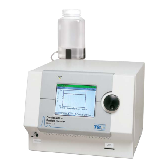
- Page 14 1-1 Model 3775 Condensation Particle Counter ......1-2 2-1 View of Fill Bottle Bracket Mounting ........2-3 3-1 View of the Model 3775 CPC LCD Display and Control Knob ................3-2 3-2 Back Panel of the Model 3775 CPC ........3-3 3-3 Sample Digital Pulse from Pulse Output Port at the Back Panel of the CPC..............
- Page 15 8-13 View of Instrument Interior Showing Tee Connection for External Pump .............. 8-20 T a b l e s 2-1 Model 3775 CPC Packing List ..........2-1 7-1 Signal Connections for RS-232 Configurations ....7-6 8-1 3775 CPC Maintenance and Replacement Kits....8-2 8-2 Filter Replacement Schedule..........8-6...
-
Page 17: About This Manual
A b o u t T h i s M a n u a l P u r p o s e This is an operation and service manual for the Model 3775 Condensation Particle Counter (CPC). O r g a n i z a t i o n... -
Page 18: Related Product Literature
Appendix A: Specifications This appendix lists the specifications of the Model 3775 Condensation Particle Counter. Appendix B: Firmware Commands This appendix lists all the serial commands for communications between the CPC and the computer. Appendix C: References This appendix lists all of the references that have been used within the text of the manual. -
Page 19: Getting Help
G e t t i n g H e l p To obtain assistance with the Model 3775 Condensation Particle Counter contact Customer Service: TSI Incorporated 500 Cardigan Road Shoreview, MN 55126 USA Fax: (651) 490-3824 Telephone: 1-800-874-2811 (USA) or (651) 490-2811 E-mail Address: technical.service@tsi.com... -
Page 21: Product Description
(SMPS ) spectrometer to measure particle size distribution. The successor to the Model 3022A CPC, the Model 3775 CPC offers many new features and improvements: Detects particles down to 4 nanometers Faster response to rapid changes in aerosol concentration (T •... -
Page 22: How It Works
Model 3775 Condensation Particle Counter H o w i t W o r k s In the Model 3775 Condensation Particle Counter (CPC), an aerosol sample is drawn continuously through a heated saturator where butanol is vaporized and diffuses into the aerosol sample stream. - Page 23 Instrument flows are controlled by a variable orifice and an orifice operated at a critical pressure. The Model 3775 CPC uses a laser-diode light source and diode photodetector to collect scattered light from particles. An internal microprocessor is used for instrument control and data processing.
-
Page 25: Packing List
U n p a c k i n g a n d S e t t i n g u p t h e C P C Use the information in this chapter to unpack the Model 3775 Condensation Particle Counter (CPC) and set it up. -
Page 26: Unpacking
Service,” gives instructions for returning the CPC to TSI Incorporated. S e t t i n g U p This section contains instructions for setting up the Model 3775 CPC. Follow the instructions in the order given. Remove Protective Caps Remove all protective caps from the inlet sample port and exit flow ports at the back of the instrument. -
Page 27: Filling The Fill Bottle With Butanol
Figure 2-1 View of Fill Bottle Bracket Mounting Find the Fill Bottle in the accessory kit. Connect the bottle tube fitting to the Butanol Fill port at the back panel of the instrument. Position the bottle with the fitting oriented for minimal stress on the tubing connector on the back panel and place the bottle in the bracket. -
Page 28: Apply Power To The Cpc
CPC is exposed to ambient air. Note: If the CPC has n-butyl alcohol (butanol) in the reservoir, be very careful when moving the CPC. See “Moving and Shipping the CPC” section for details. Model 3775 Condensation Particle Counter... -
Page 29: Front Panel
Use the information in this chapter to become familiar with the location and function of controls, indicator, and connectors on the Model 3775 Condensation Particle Counter (CPC). F r o n t P a n e l The main components of the front panel include the color LCD display, rotate/select control knob, aerosol inlet, particle indicator light, and flash memory card slot. -
Page 30: Aerosol Inlet
Figure 3-1 View of the Model 3775 CPC LCD Display and Control Knob Aerosol Inlet The Aerosol Inlet is located on the front panel. The inlet consists of a ¼” OD tube suitable for use with common tube fittings. Permanent fittings with metal locking ferrules should be avoided since this may inhibit removal of the front panel in the event service is required. -
Page 31: Back Panel
B a c k P a n e l As shown in Figure 3-2, the back panel of the Model 3775 CPC has power and data connections, analog input/output connections, pump exhaust port, makeup air port, butanol fill and drain ports, and cooling fan. -
Page 32: Rs-232 Serial Connections
Typical (nominal) pulse widths are 2.5 microseconds (see Figure 3-3) for the 3775 CPC. To provide accurate pulse counts, use a counter that is capable of counting pulses with a width of 50 nanoseconds or less. -
Page 33: Ethernet Communication Port
Sample Digital Pulse from Pulse Output Port at the Back Panel of the CPC Ethernet Communication Port Instrument status including particle concentration of the Model 3775 CPC can be monitored remotely from a local area network or over the internet using the Ethernet communication port. Ethernet communications are described further in Chapter 7, “Computer... -
Page 34: Butanol Fill Port
CPC. It is secured to the chassis with six screws on the bottom. The six screws can be loosened to remove the cover and access to the interior of the Model 3775 CPC. Model 3775 Condensation Particle Counter... -
Page 35: Left Side Panel
L e f t S i d e P a n e l The left side panel refers to the side panel on the left when facing the front panel of the instrument. As shown in Figure 3-4, it includes a clear removable butanol reservoir cover plate that is used to view the liquid level in the saturator, and to access the saturator wick for easy removal before instrument shipment. -
Page 36: Internal Components Of The Model 3775 Cpc
12. Pressure transducers 7. Butanol fill filter 13. Power supply Figure 3-5 Internal Components of the Model 3775 CPC Sensor Assembly The sensor assembly consists of the heated saturator, liquid wick, cooled condenser, and optics. In this assembly, sample particles serve as condensation nuclei and are grown in a supersaturated atmosphere of butanol. - Page 37 Valves and Variable Orifice The Model 3775 CPC uses valves and a variable orifice for air flow control and butanol filling and draining. A three-way solenoid valve controls the inlet flow rate, switching between high and low inlet sample flow modes.
-
Page 38: Pressure Transducers
Status screen. Electronics Boards Five electronics boards identified in Figure 3-6, are used in the Model 3775. The boards include Main PC board, laser board, detector board, communication connector board, and flash memory board. Figure 3-6 Electronics Boards Inside the Model 3775 CPC 1. -
Page 39: Basic Instrument Functions
High and Low Flow Modes The Model 3775 CPC has user-selectable high and low inlet sample flow modes. The high inlet sample flow mode, 1.5 L/min, is preferred for smaller particles because particles are transported more quickly through sampling lines, reducing particle diffusion losses. -
Page 40: Internal Data Logging
Chapter Flow Rate Control The Model 3775 CPC uses a critical orifice and a variable orifice to accurately control the air flows in the instrument. The critical orifice operates at or below the critical pressure ratio to control the 0.3 L/min (nominal) volumetric aerosol flow. -
Page 41: Temperature Control
Temperature Control The temperatures of the condenser, saturator, and optics are nominally maintained at 14°C, 39°C and 40°C, respectively, with specified ambient temperatures in the operating range of 10 to 35°C. Temperatures are controlled through feedback circuits on the main electronics board, and are displayed in the Status menu on the front panel. -
Page 43: Operating Precautions
C o n t r o l K n o b a n d L C D D i s p l a y The 3775 CPC measurement data is presented on a 3.5” × 4.5” quarter VGA color LCD display. Instrument functions are accessed on the display using the rotate/select control knob. -
Page 44: Warm-Up
M a i n D a t a P r e s e n t a t i o n S c r e e n The Main Data Presentation Screen is shown in Figure 4-2. This screen appears automatically once the warm-up is complete or can be displayed prior to the completion of the warm-up by depressing Model 3775 Condensation Particle Counter... -
Page 45: Cpc Main Data Presentation Screen During Operation
Figure 4-2 shows a concentration of approximately 2 × 10 p/cc. The graph was updated each second over an interval of 24 seconds. Note: For the 3775, the maximum concentration displayed is 10 particles/cm . At concentrations above 10 particles/cm... -
Page 46: Display Showing Cursor
Flash Memory Card. START is displayed once STOP is pressed. Press START START to initiate update of the graphical display, and to save to the Flash Memory Card. Figure 4-3 Display Showing Cursor Model 3775 Condensation Particle Counter... -
Page 47: Display Header
Figure 4-4 Display After the MENU Function is Selected Display Header Two bars are present at the top of the display screen to provide information on instrument operation. Status Bar Color The status bar background changes from red to green as the instrument reaches normal operating conditions (Status: Normal). -
Page 48: Exit (Top And Bottom)
Data Average Period. The graph x-axis scale is determined by the selected average period as described in the table below. This option is deactivated while data is logging into the flash memory card. Model 3775 Condensation Particle Counter... -
Page 49: Auto Water Removal
Auto Water Removal This option provides ON/OFF control for the automatic water removal feature of the Model 3775 CPC. This feature is used in hot/humid environments to eliminate contamination of the butanol working fluid by condensed water vapor. Water removal keeps the CPC operating at peak performance. -
Page 50: Inlet Flow Mode
Totalizer Mode. Totalizer Mode Screen is displayed as shown in Figure 4-6. The CPC will count time and particles once the START button is selected. Concentration is calculated from the time and count data. Figure 4-6 Totalizer Mode Data Screen Model 3775 Condensation Particle Counter... -
Page 51: Totalizer Time
Totalizer Time Use this option with the Totalizer Mode to select the time period for accumulating counts. Three options are available; 60 seconds, 60 minutes and Continuous. Sampling stops once the time is complete. Sampling may be ended manually prior to the end of a sampling period by selecting STOP. -
Page 52: Drain
Refer to Figure 4-2 depicting the graph while reading this section. Figure 4-7 shows the options possible when Graph Options is selected from the User Settings Menu. A description of these options is provided below: 4-10 Model 3775 Condensation Particle Counter... -
Page 53: Graph Options Menu
Figure 4-7 Graph Options Menu Select from Log or Linear concentration display. Y-Axis Scale Max Y-Axis Value Use this option to pick the upper limit for concentration display on the graph. Concentration is presented in particles per cubic centimeters (p/cc). Autoscale automatically scales the graph based on the highest concentration. -
Page 54: Status
Status shows Multiple Errors, statuses that deviate from normal operating parameters are in red color. The Status menu can be used as a diagnostic tool. Figure 4-8 Status MENU Option Highlighted. 4-12 Model 3775 Condensation Particle Counter... -
Page 55: Saturator Temperature
Figure 4-9 Status Screen Information provided in the Status screen is described below. Saturator Temperature Saturator temperature is 39°C when the instrument warm up is complete and the instrument has stabilized. The saturator provides saturated butanol vapor that mixes with aerosol particles. Condenser Temperature Particle growth occurs in the condenser as butanol vapor from the saturator is cooled and condenses on sampled aerosol particles. -
Page 56: Aerosol Flow Rate
LCD display and saved to the Flash Memory Card during data logging. The analog input data can also be displayed along with particle ® concentration in the Aerosol Instrument Manager software. 4-14 Model 3775 Condensation Particle Counter... -
Page 57: Using The Flash Memory Card
U s i n g t h e F l a s h M e m o r y C a r d Particle concentration data and analog input data can be saved to a Flash Memory Card inserted in the slot at the lower right corner of the front panel. -
Page 58: Aerosol Instrument Manager ® Software
M o v i n g a n d S h i p p i n g t h e C P C Make sure the Model 3775 CPC is turned off and remains upright while moving the instrument. There is no need to drain the CPC before moving the CPC. -
Page 59: Chapter 5 Technical Description
C H A P T E R 5 T e c h n i c a l D e s c r i p t i o n The Model 3775 CPC is a continuous-flow condensation particle counter that detects particles as small as 4 nanometers (50% detection efficiency) in diameter. -
Page 60: History
He made several improvements to his invention and his portable dust counter was used for many years (Aitken [1890–91]). Model 3775 Condensation Particle Counter... -
Page 61: Two-Flow Mixing Cnc
Other significant developments in adiabatic-expansion CNCs include the use of electrical photodetectors to measure the light attenuation from cloud formation (Bradbury and Meuron [1938], Nolan and Pollak [1946], Rich [1955], Pollak and Metneiks [1959]); the use of under- and overpressure systems; and automation using electrically controlled valves and flow systems. - Page 62 0.3 L/min. TSI’s Model 3020 CNC was replaced in 1988 by the Model 3022A, which was replaced again in 2005 by the Model 3775 CPC. Both the Model 3775 CPC and the 3785 WCPC use the photometric mode of operation to...
-
Page 63: Design Of The Cpc
Currently, six CPCs (Models 3772, 3775, 3776, 3782, 3785, and 3786) are also commonly used with submicron size-distribution measurement systems such as the Scanning Mobility Particle Sizer (SMPS ) Spectrometers (TSI Model 3936). D e s i g n o f t h e C P C... -
Page 64: Flow Schematic Of The Model 3775 Cpc
The Model 3775 CPC uses two modes of particle counting: single- particle counting mode and photometric mode. At concentrations below 50,000 particles/cm , individual electrical pulses generated by light scattered from individual droplets are counted, employing a continuous “live-time” coincidence correction algorithm to improve counting accuracy. -
Page 65: Flow System
Flow System Refer to Figure 5-1 while reviewing information on instrument flow provided in this section. The CPC relies on an on-board high-vacuum pump to maintain constant critical flows through a critical orifice and a variable orifice. The CPC has two inlet flow options: high flow mode, nominally 1.5 L/min (1500 cm /min) and low flow mode, nominally 0.3 L/min (300 cm... -
Page 66: Counting Efficiency And Response Time Of The Cpc
50% of particles are detected. The curve fit shown in Figure 5-2 is based on testing of three 3775 CPCs using sucrose particles generated by TSI Model 3480 Electrospray Aerosol Generator and size classified with TSI Model 3080 Electrostatic Classifier and Model 3085 Nano Differential Mobility Analyzer (DMA) . - Page 67 CPC reading to reach 95% of a concentration step change, is about 4 sec in high flow mode and about 5 sec in low flow mode for the 3775 CPC. Figure 5-3 shows the response time curves in both flow modes. The curves are based on averaging of three CPCs.
- Page 68 High Flow Low Flow Time, sec Figure 5-3 Response Time of 3775 CPC 5-10 Model 3775 Condensation Particle Counter...
- Page 69 Model 3775 Condensation Particle Counter (CPC). The Model 3775 CPC has two modes for particle counting: Concentration mode, where data is presented as particle concentration in p/cc, updated each second on the display (the maximum time resolution is tenth of a second).
- Page 70 The actual particle concentration therefore equals the number of counted particles divided by the live time and the aerosol flow rate. Model 3775 Condensation Particle Counter...
- Page 71 10 particles/cm . The Model 3775 CPC DC voltage is recorded at the different concentration calibration points. To determine the actual salt concentration used for the calibration points, a diluter and second CPC “standard”...
-
Page 73: Chapter 7 Computer Interface And Commands
C o m m a n d s This chapter provides computer interface and communications information for the Model 3775 Condensation Particle Counter (CPC). Information on the Flash Memory Card is also provided. C o m p u t e r I n t e r f a c e This section includes descriptions on USB, Ethernet connections, RS-232, and the Flash Memory Card. -
Page 74: Digi Device Discovery Screen
4. Talk with your network administrator to verify the correct network settings this device should operate at. If needed, the MAC address can be located on the back of the instrument or in this pop-up window. Fill in the appropriate information and click Save. Model 3775 Condensation Particle Counter... -
Page 75: Configure Network Settings Screen
Figure 7-2 Configure Network Settings Screen 5. Close the device discovery program and restart the CPC. It takes about a minute for the Ethernet to initialize. 6. If the CPC is in the same subnet as the computer, start the device discovery program Discovery.exe and click on Open web interface. -
Page 76: Main Screen Html Page
LINE 1: “TSI CPC DATA VERSION 1” LINE 2: start time of this file (the first number is the total number of seconds elapsed from midnight Jan. 1, 1970) LINE 3: data average interval in seconds Model 3775 Condensation Particle Counter... -
Page 77: Rs-232 Serial Communications
RS-232-type devices. RS-232 is a popular communications standard supported by many mainframe computers and most personal computers. The Model 3775 CPC has two 9-pin, D-type subminiature connectors on the back panel labeled Serial 1 and Serial 2. Figure 7-5 shows the connector pins on the serial ports;... -
Page 78: Rs-232 Connector Pin Designations
In this specification, values enclosed by “<>” indicate ASCII characters/values sent/received. For example, <,> indicates the comma was sent or received via the communications channel. Integers are 32-bit values. Floating point are IEEE() 32-bit values. Model 3775 Condensation Particle Counter... -
Page 79: Read Commands
Integer and floating point values are “C” string compatible ASCII- encoded. For example, an integer value of <11011100101110101001100001110110> binary, would be sent as <3703216246>. When char, integer or hex-decimal data is sent with more than one digit, leading zeros should always be left off. If the value of the data is zero, then one zero must be sent. - Page 80 Connect to Serial 1 of the Model 3775 CPC and perform the following steps: 1. Open the HyperTerminal program by selecting: Start|Programs|Accessories|Communications| HyperTerminal. 2. Enter a name for the connection, for example, TSI-3775. Figure 7-6 Connection Description Screen 3. Enter the communications (COM) port.
- Page 81 Figure 7-7 Connect To Dialog Box 4. Enter the port settings described below and click OK. Figure 7-8 Port Settings Dialog Box Computer Interface and Commands...
- Page 82 Appendix B. To obtain the list from HELP command, select Transfer|Capture Text… and then HELP ALL in the terminal window lets you capture all the help commands to a text file for easy reference. 7-10 Model 3775 Condensation Particle Counter...
-
Page 83: Chapter 8 Maintenance And Service
Static preventative measures should be observed when handling any printed circuit board connectors. Regular maintenance of the Model 3775 Condensation Particle Counter (CPC) will help ensure years of useful operation. The frequency of service depends on the frequency of use and the cleanliness of the air measured. -
Page 84: 3775 Cpc Maintenance And Replacement Kits
TSI to keep your CPC operating for many years. Parts are available in kits listed below. Please contact your TSI representative for details and purchase of these items. Table 8-1 3775 CPC Maintenance and Replacement Kits TSI Part No. Name Description 1031484... - Page 85 TSI Part No. Name Description 1031490 Orifice Flow Replacement Control Kit 3775 critical orifices. 1031492 Kit, Charcoal Five (5) large Filter, large, CPC charcoal filters used to remove butanol from exhaust (~ten- effectiveness for each filter). 1031493 Kit, Charcoal Five (5) small...
-
Page 86: Draining Butanol From The Butanol Reservoir
To drain the butanol reservoir: 1. Connect butanol drain bottle (from the accessories) to the drain fitting on the back of the CPC using the mating quick-connect fitting. 2. Place the drain bottle on the floor. Model 3775 Condensation Particle Counter... -
Page 87: Filter Replacement Schedule
C h a n g i n g t h e F i l t e r s The Model 3775 CPC use three particulate filters and two liquid filters. The particulate filters are for the exhaust flow, bypass air flow, and makeup air flow. -
Page 88: Replacing The Exhaust Filter
Lift the cover up. Do not remove the screws holding the clear butanol reservoir cover. 3. Before replacing the filter, note the direction arrow on the filter that points to the back of the instrument. Model 3775 Condensation Particle Counter... -
Page 89: Replacing The Bypass Air Filter
4. Remove the tubing from the barbed fitting at the back of the filter. 5. Unscrew the filter and separate it from the threaded bulkhead panel fitting. Discard the old filter after removing fittings at both ends. 6. Find in the accessory kit the new exhaust filter (P/N 1602094) with the stainless steel fitting and the elbow plastic fitting. -
Page 90: Replacing The Makeup Air Filter
(they don’t have to be fully removed). Lift the cover up. Do not remove the screws holding the clear butanol reservoir cover. 3. Locate the filter in Figure 8-3. 4. Remove the tubing from both ends of the filter. Model 3775 Condensation Particle Counter... -
Page 91: Replacing The Butanol Fill Filter
5. Replace the filter with the one in the accessory kit (P/N 1602088). This filter has no preferred direction,. Butanol Fill Filter The butanol fill filter is found in the fill line leading from the butanol bottle (Figure 8-4). Figure 8-4 Replacing the Butanol Fill Filter 1. -
Page 92: Micro-Pump Filter
Be careful not to pull the tubing off the pump fitting or fitting in the saturator. 6. Install a new filter (P/N 1500192) from the accessory kit. This filter has no preferred direction. 8-10 Model 3775 Condensation Particle Counter... -
Page 93: Front Panel Screw Removal
Figure 8-5 Front Panel Screw Removal Figure 8-6 Micro-Pump Filter, Shown Behind the Opened Front Panel Maintenance and Service 8-11... -
Page 94: Removing And Installing The Saturator Wick
Figure 8-7. Make sure the blue O-ring gasket seal is retained if it becomes unseated. Put paper towels on the table under the reservoir to absorb any butanol that spills out. 8-12 Model 3775 Condensation Particle Counter... -
Page 95: Saturator Wick Removal
Figure 8-7 Saturator Wick Removal 6. Insert a small flat-blade screwdriver in the notch at the side of the wick and pry the wick out as shown in Figure 8-8. You may need to use pliers if the wick is soaked with butanol (see Figure 8-9). -
Page 96: Prying The Saturator Wick Out
Figure 8-8 Prying the Saturator Wick Out Figure 8-9 Pulling the Saturator Wick Out Using Pliers with Minimal Force 8-14 Model 3775 Condensation Particle Counter... -
Page 97: Installing A Saturator Wick
Figure 8-10 Installing a Saturator Wick B y p a s s / M a k e u p A i r F l o w A d j u s t m e n t Refer to the flow schematic in Figure 5-1. High inlet flow is adjustable using the bypass/makeup air variable orifice. -
Page 98: Maintenance Of The Critical Orifice
Current nozzle differential and crifical orifice differential pressure are both displayed on the Status screen shown in Figure 4-9, Chapter 4. Note that the orifice differential pressure can indicate 8-16 Model 3775 Condensation Particle Counter... - Page 99 there is sufficient vacuum pressure even when the orifice itself is clogged because the vacuum pump may pull less air flow through the sensor. A plugged orifice is best determined by measuring the inlet flow while the instrument is in the low flow operation mode. Inlet flow measurement is made using a volumetric flowmeter capable of accurately measuring 0.3 L/min flow.
-
Page 100: Top View Of Instrument Showing Critical Orifice In Optics Block
8. Apply thread sealing tape or compound and re-install the orifice. 9. Reconnect the plastic tubing. 10. Verify flow as described earlier. Figure 8-11 Top View of Instrument Showing Critical Orifice in Optics Block 8-18 Model 3775 Condensation Particle Counter... -
Page 101: Top View Of Instrument Showing Pump Top And Pump Inlet And Exhaust Fittings And Tubing
I n s t a l l a t i o n o f a n E x t e r n a l V a c u u m P u m p It is possible to use an external pump with your CPC. The pump must provide sufficient vacuum to maintain a critical pressure across the aerosol flow orifice and bypass/makeup air variable orifice, while providing adequate inlet flow for instrument operation. -
Page 102: View Of Instrument Interior Showing Tee Connection For External Pump
To eliminate the possibility of butanol contamination, follow the directions in the following section for “Flooded Instrument.” If the false count problem continues, it is most likely due to a leak. Contact TSI for assistance. 8-20 Model 3775 Condensation Particle Counter... -
Page 103: Troubleshooting
E r r o r M e s s a g e s a n d T r o u b l e s h o o t i n g The table below provides basic information on the errors generated by the Model 3775 CPC, and suggestions for corrective action. When an error occurs, the status bar at the top of the screen turns red and the error is displayed e.g., “Saturator temp out of range.”... - Page 104 Check for disconnected pressure tubes to the pressure transducers. Check for signs of liquid in the pressure lines. This will defeat the pressure readings and may indicate a flooded instrument (see below). 8-22 Model 3775 Condensation Particle Counter...
-
Page 105: Calibrating And Entering New Orifice Flow Data
Description Problems/Suggestions Flooded instrument Butanol liquid is present in the Although the 3775 CPC has been designed to resist instrument optics causing a flooding, it can occur if the instrument is shipped variety of problems including without properly drying or removing a wet wick. -
Page 106: Orifice Calibration
6. Connect your computer to the serial port (Serial 1) at the back of the CPC instrument. 7. Type in the serial command for changing the 3775 aerosol flow rate "SAF,x", if necessary, where x is the flow rate in cm /min. -
Page 107: Returning The Cpc For Service
T e c h n i c a l C o n t a c t s If you have any difficulty installing the CPC, or if you have technical or application questions about this instrument, contact an applications engineer at TSI Incorporated, (651) 490-2811. - Page 109 A P P E N D I X A S p e c i f i c a t i o n s Table A-1 contains the operating specifications for the Model 3775 Condensation Particle Counter (CPC). These specifications are subject to change without notice.
-
Page 110: Model 3775 Cpc Specifications
BNC connector, TTL level pulse, 50-ohm termination, nominally 2.5 microseconds wide Software ....... Aerosol Instrument Manager® software (RS-232 and USB compatible) Calibration ......Recommended annually Power requirements ....100 to 240 VAC, 50/60 Hz., 335 W maximum Model 3775 Condensation Particle Counter... - Page 111 Table A-1 Model 3776 CPC Specifications Physical features LCD TFT QVGA (320 ×240 pixel) 5.7-inch color display, Front panel ......aerosol inlet, LED particle indicator light, rotate/select control knob, flash memory card slot Back panel......Power connector, USB, Ethernet, two 9-pin D-sub serial connectors, two BNC inputs, two BNC outputs, fan, butanol-fill connector, butanol-drain connector, makeup- air port, pump-exhaust port, fill bottle and bracket...
- Page 113 A P P E N D I X B F i r m w a r e C o m m a n d s The firmware commands are divided into the following categories: READ Commands SET Commands MISC (MISCELLANEOUS) Commands HELP Commands READ commands are used to read parameter from the instrument (flow rates, temperatures, etc.).
- Page 114 Www Mmm dd hh:mm:ss yyyy where Www is the weekday Mmm is the month in letters dd is the day of the month hh:mm:ss is the time yyyy is the year Example: Mon Jun 11 11:05:08 2006 Model 3775 Condensation Particle Counter...
- Page 115 Read the instrument errors Returns: 16-bit integer in hexadecimal format. The parameter is in error if the bit is set. Bit 0x0001 => Saturator Temp Bit 0x0002 => Condenser Temp Bit 0x0004 => Optics Temp Bit 0x0008 => Inlet Flow Rate Bit 0x0010 =>...
- Page 116 Legacy command to read the condenser temperature in degrees Celsius Legacy command to read the saturator temperature in degrees Celsius Legacy command to read the optics temperature in degrees Celsius Legacy command to read the instrument status. Returns: READY or NOTREADY Model 3775 Condensation Particle Counter...
- Page 117 Legacy command to read the photometric voltage (3775 only) Returns: 0.000–2.500 volts Example: 2.013 Legacy command to read the concentration in p/cc Read the version string. Returns: Model 377x Ver B.B.B S/N AAAAAAAA S E T C o m m a n d s...
- Page 118 40.0 degrees C) SAWR Set the auto water removal function on/off Params: 0–Off 1–On Example: SAWR,1 (turns on water removal) Set analog output voltage Params: v => 0.000–10.000 Example: SVO,4.482 (sets the output voltage at 4.482 volts) Model 3775 Condensation Particle Counter...
- Page 119 Set analog output voltage proportional to concentration. The analog output is 0 to 10V. Params: 0 => Off 1 => 1E1 2 => 1E2 3 => 1E3 4 => 1E4 5 => 1E5 (CPC100 only) Example: SAO,4 (A concentration reading of 1E4 will equal 10V) SCOM Setup auxiliary comport...
- Page 120 Turn coincidence correction on/off (3772 and 3771 only) Params: 0 => Off 1 => On Example: SCC,1 (turns coincidence correction on) Set the 3775 aerosol flow rate in cc/min (3775 only) Params: Q => 200–400 cc/min Example: SAF,300 (changes the aerosol flow rate to 300 cc/min)
- Page 121 2) Legacy command to turn the pump off Legacy command to turn the pump on Legacy command to set the inlet flow to 0.3 L/min (3775 and 3776 only) Legacy command to set the inlet flow to 1.5 L/min (3775...
- Page 122 Change the active flash card directory (except 3771) CAL3775 Set the 3775 Photometric calibration table (3775 only) Format: CAL3775,x,y Where: x => photometric voltage 100 in volts y => concentration in p/cc Example: CAL3775,101,2.03e5 (a photometric voltage of 1.01 V will result in a concentration of 2.03e5 p/cc)
- Page 123 A P P E N D I X C R e f e r e n c e s The following sources have been used in the text of this manual. Agarwal, J.K. and G.J. Sem [1980] “Continuous Flow Single-Particle-Counting Condensation Nuclei Counter”...
- Page 124 Presented at the 12th International Conference on Atmospheric Aerosols and Nucleation, Vienna, Austria. Keston, J., Reineking, A. and J. Porstendorfer (1991) “Calibration of a TSI Model 3775 Condensation Particle Counter.” Aerosol Science and Technology, 15, 107-111. Kousaka, Y. T. Nida, K. Okuyama and H., Tanaka [1982] “Development of a Mixing-Type Condensation Nucleus Counter”...
-
Page 125: Appendix C References
Pollak, L.W. and A.L. Metnieks [1959] “New Calibration of Photoelectric Nucleus Counters” Geofis. Pura Appl., Vol. 43, pp. 285–301 Quant, F. R., R. Caldow, G.J. Sem, T.J. Addison [1992] “Performance of Condensation Particle Counters with Three Continuous-Flow Designs”, presented as a poster paper at the European Aerosol Conference, Oxford England, Sept. - Page 126 Stolzenburg, M.R. [1988] “An Aerosol Size Distribution Measuring System” Ph.D. Thesis, University of Minnesota, Minneapolis, Minnesota, July Model 3775 Condensation Particle Counter...
- Page 127 8-17, 8-24 Model 3762, 5-3 butanol, vii, 2-3, 3-6, 3-9 Model 3771, 5-3 caution, 2-4 Model 3772, 5-3 drain port, 3-6 Model 3775, 5-4 draining, 4-16 Model 3776, 5-4 butanol bottle, 3-6 Model 3781, 5-4 butanol consumption, 4-8 Model 3782, 5-4...
- Page 128 3-12 bracket mounting, 2-3 internal vacuum pump, 1-3, 3-6, 5-4, 8-6, 8-19, filling with butanol, 2-3 8-20 filter, 3-9 filter replacement schedule, 8-6 filters Kelvin diameter, 5-1, 5-2 changing, 8-5 replacing, 8-5 Index-2 Model 3775 Condensation Particle Counter...
-
Page 129: Chapter 6 Particle Counting
Model 3776 Ultrafine Condensation Particle Counter manual, xviii laser board, 3-10 Model 3781 Water-based Condensation Particle laser current, 4-14 Counter manual, xviii laser power, 3-12, 4-5, 4-14, 5-5 Model 3781 WCPC, 5-4 display, A-2 Model 3782 Water-based Condensation Particle status, 8-23 Counter manual, xviii laser safety, vii Model 3782 WCPC, 5-4... - Page 130 SET commands, 7-7, B-1, B-5 Y–Z setting up, 2-1, 2-2 shipping instrument, 4-16 y-axis scale, 4-11 signal connections for RS-232 configurations, 7-6 single count mode, 6-1 solenoid valve, 3-9 specifications, A-1 start, 4-4 static prevention measures, 8-1 Index-4 Model 3775 Condensation Particle Counter...
-
Page 131: Reader's Comments Sheet
Please help us improve our manuals by completing and returning this questionnaire to the address listed in the “About This Manual” section. Feel free to attach a separate sheet of comments. Manual Title Model 3775 Condensation Particle Counter P/N 1980527 Rev D 1. Was the manual easy to understand and use? - Page 133 TSI Incorporated Headquarters—Tel: +1 651 490 2811 Toll Free: 1 800 874 2811 E-mail: particle@tsi.com Tel: +44 1494 459200 E-mail: tsiuk@tsi.com France Tel: +33 491 95 21 90 E-mail: tsifrance@tsi.com Germany Tel: +49 241 523030 E-mail: tsigmbh@tsi.com Sweden Tel: +46 8 595 13230 E-mail: tsiab@tsi.com India Tel: +91 80 41132470 E-mail:...
Need help?
Do you have a question about the 3775 and is the answer not in the manual?
Questions and answers