Air Lift LoadLifter 5000 Ultimate Installation Manual
Adjustable air helper springs
Hide thumbs
Also See for LoadLifter 5000 Ultimate:
- Installation manual ,
- Installation manual (22 pages) ,
- Installation manual (28 pages)
Table of Contents
Advertisement
Quick Links
A D J U S TA B L E A I R H E L P E R S P R I N G S
TOW AND HAUL WITH SAFETY AND COMFORT
Kit Number
88365
INSTALLATION GUIDE
For maximum effectiveness and
safety, please read these instructions
completely before proceeding with
installation.
Failure to read these instructions can result in an
incorrect installation.
MN-944 • (011411) • ERN 8033
TM
Advertisement
Table of Contents

Related Manuals for Air Lift LoadLifter 5000 Ultimate


Summary of Contents for Air Lift LoadLifter 5000 Ultimate
- Page 1 A D J U S TA B L E A I R H E L P E R S P R I N G S TOW AND HAUL WITH SAFETY AND COMFORT Kit Number 88365 INSTALLATION GUIDE For maximum effectiveness and safety, please read these instructions completely before proceeding with installation.
-
Page 3: Table Of Contents
Tools List . . . . . . . . . . . . . . . . . . . . . . . . . . . . . . . . . . . . . . . . . . . . . . . . . . . . . . . . . . . . 4 Installing the LoadLifter 5000 Ultimate System . . . . . . . . . . . . . . . 4 Getting Started . -
Page 4: Introduction
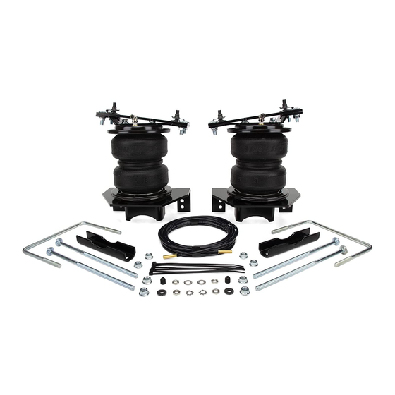
. The internal jounce bumper replaces the factory bumper and allows the air springs to safely be run at zero air pressure . LoadLifter 5000 Ultimate kits are recommended for most 3/4 and 1 ton pickups and SUVs with leaf springs, and provide up to 5,000 pounds of load- leveling support with air adjustability from 5-100 PSI . -
Page 5: Installation Diagram
LoadLifter 5000 Ultimate Installation Diagram Left-hand side shown (driver side) Right-hand side shown (passenger side) fig. 1 NOTE: PROFESSIONAL MECHANICAL SKILLS ARE NECESSARY IN ORDER TO COMPLETE THE INSTALLATION OF THIS KIT . MN-944... -
Page 6: Hardware List
*Not shown in fig. 1. 17361 3/8”-16 x 1 .25” Carriage Bolt ....12 Missing or damaged parts? Call Air Lift customer STOP! service at (800) 248-0892 for a replacement part . - Page 7 LoadLifter 5000 Ultimate 2 . Mark the bottom of the right-hand and left-hand coil springs and lower spring seat mounts with chalk or a paint marker to make sure the spring is put back the same way it is removed (fig. 3).
- Page 8 LoadLifter 5000 Ultimate 6 . Grind the welds removed, down flush to the frame with the grinder. (fig. 6). fig. 6 7 . Spray the frame with black paint or undercoating to cover the bare surface, from grinding the welds flush previously (fig. 7). Repeat for both sides.
- Page 9 LoadLifter 5000 Ultimate fig. 9 9 . Only tighten the bolt to where it can still slide in the slot . 10 . Set the frame bracket (with the socket head bolt in it), on the frame, with the flange pointing up .
- Page 10 LoadLifter 5000 Ultimate TECHNICAL NOTE If possible, with the bracket in position, use a 21/64 (or closest) centering punch to fit into the hole and center-punch the frame for an exact center of the hole. fig. 12 13 . Center-punch the frame and drill a 1/4” hole (fig. 13). Start a 5/16” self-tapping screw (K) into the hole, making sure it is straight, and tighten it enough to form the threads needed to set the screw (fig.
-
Page 11: Assembling The Air Springs
LoadLifter 5000 Ultimate 16 . Install two more self-tapping screws (K) in the side, making sure the flat head portion of the bolt is flush to the bracket, and torque to 15 ft-lbs. (fig. 15). Repeat for the other side. - Page 12 LoadLifter 5000 Ultimate H I J fig. 17 fig. 18 5 . Flip the air spring assemblies upside down and set a roll plate (E) over the air spring (same as in step one) . 6 . Position the air spring assemblies so that the fittings are outboard and away from each other (fig.
-
Page 13: Installing The Assemblies
LoadLifter 5000 Ultimate Right- side Left side assembly assembly (passenger (driver side) side) using using Lower lower bracket Bracket (C1) . (C2) . fig. 20 INSTALLING THE ASSEMBLIES 1 . Index a 3/8” carriage bolt (L) into the opening on the front of the driver side assembly as shown (fig. - Page 14 LoadLifter 5000 Ultimate fig. 23 4 . Insert another 3/8” carriage bolt (L) through the remaining hole in the front side of the bracket (fig. 24). fig. 24 5 . It will be necessary to use a socket with an extension to reach the inside threads on the carriage bolt previously set into position (fig.
- Page 15 LoadLifter 5000 Ultimate 6 . Set the right hand unit assembly into position in the same way indexing the lower bracket with the tabs under the jounce bumper strike plate and, with the exception of using the slot for the carriage bolt in the lower bracket, install the carriage bolts in the same manner .
-
Page 16: Installing The Air Lines
LoadLifter 5000 Ultimate 8 . Left-side shown with the assembly bolted up to the frame bracket (fig. 29). fig. 29 INSTALLING THE AIR LINES 1 . On the passenger side only, place the provided thermal sleeve (HH) on the air line near the exhaust . - Page 17 LoadLifter 5000 Ultimate fig. 31 Good Cut Poor Cut 6 . Place a 5/16” hex nut (GG) and a star washer (FF) on the air valve . Leave enough of the inflation valve in front of the nut to extend through the hole and have room for the rubber washer (EE), flat washer (DD), and 5/16”...
-
Page 18: Installing The Heat Shield
LoadLifter 5000 Ultimate INSTALLING THE HEAT SHIELD NOTE Finished photo of heat shield installed on right-side (passenger) exhaust (fig. 34). fig. 34 1 . Bend the tabs on the heat shield to provide a 1/2” dead air space between exhaust pipe and heat shield (fig. -
Page 19: Checking For Leaks
DO NOT CUT THE AIR LINE COMPLETELY OFF AS THIS WILL NICK THE BARB AND CAUTION RENDER THE FITTING USELESS . 3 . If the preceding steps have not resolved the problem, call Air Lift customer service at (800) 248-0892 for assistance . MN-944... -
Page 20: Photos Of Finished Assemblies
LoadLifter 5000 Ultimate PHOTOS OF FINISHED ASSEMBLIES 1 . Back view of left-side (driver) assembly (fig. 37). fig. 37 2 . Back view of right-side (passenger) assembly (fig. 38). fig. 38 MN-944... -
Page 21: Before Operating
LoadLifter 5000 Ultimate Before Operating INSTALLATION CHECKLIST (To be completed by installer) Clearance test — Inflate the air springs to 60 PSI and ensure there is at least 1/2” clearance around each bellow, away from anything that might rub against them . Be sure to check the tire, brake drum, frame, shock absorbers and brake cables . -
Page 22: Product Use, Maintenance And Servicing
4 . Look for a kink or fold in the air line . Reroute as needed . If the preceding steps do not solve the problem, it is possibly caused by a failed air spring — either a factory defect or an operating problem . Please call Air Lift at (800) 248-0892 for assistance . MN-944... -
Page 23: Frequently Asked Questions
No . Adding air springs will not change the weight ratings (GAWR, GCWR and/or GVWR) of a vehicle . Exceeding the GVWR is dangerous and voids the Air Lift warranty . Q . Is it necessary to keep air in the air springs at all times and how much pressure... -
Page 24: Guidelines For Adding Air
LoadLifter 5000 Ultimate GUIDELINES FOR ADDING AIR 1 . Start with the vehicle level or slightly above . 2 . When in doubt, always add air . 3 . If the front of the vehicle dives while braking, increase the pressure in the front air bags, if equipped . -
Page 25: Choosing The Right On-Board Air Compressor System
— from inside or outside of the vehicle . • For convenient, on-the-go control of your air springs, add an Air Lift on-board air compressor system . • Air Lift on-board air compressor systems eliminate the search for gas stations that have a working compressor, saving you time, energy and money . -
Page 26: Warranty And Returns Policy
.) Air Lift 1000™ ....Lifetime Limited LoadController/Dual™ ..2 Year Limited RideControl™... -
Page 27: Replacement Information
LoadLifter 5000 Ultimate Replacement Information If you need replacement parts, contact the local dealer or call Air Lift customer service at (800) 248-0892 . Most parts are immediately available and can be shipped the same day . Contact Air Lift Company customer service at (800) 248-0892, first if: •... - Page 28 Thank you for purchasing Air Lift products — the professional installer’s choice! Air Lift Company • 2727 Snow Road • Lansing, MI 48917 or PO Box 80167 • Lansing, MI 48908-0167 Toll Free (800) 248-0892 • Local (517) 322-2144 • Fax (517) 322-0240 • www .airliftcompany .com...
Need help?
Do you have a question about the LoadLifter 5000 Ultimate and is the answer not in the manual?
Questions and answers