Air Lift LoadLifter 5000 Ultimate Installation Manual
2005-10 ford super duty
4wd (single- and dual-rear wheel)
loadlifter series
Hide thumbs
Also See for LoadLifter 5000 Ultimate:
- Installation manual ,
- Installation manual (20 pages) ,
- Installation manual (22 pages)
Table of Contents
Advertisement
S E R I E S
2005-10 Ford Super Duty
Kits 57398 | 88398 | 89398
4WD (Single- and dual-rear wheel)
MN-1053 • (021707) • ECR 8540
For maximum effectiveness and safety, please read these instructions
completely before proceeding with installation.
Failure to read these instructions can result in an incorrect installation.
Installation
TM
Guide
Advertisement
Table of Contents

Subscribe to Our Youtube Channel
Related Manuals for Air Lift LoadLifter 5000 Ultimate


Summary of Contents for Air Lift LoadLifter 5000 Ultimate
- Page 1 Installation Guide S E R I E S 2005-10 Ford Super Duty Kits 57398 | 88398 | 89398 4WD (Single- and dual-rear wheel) For maximum effectiveness and safety, please read these instructions completely before proceeding with installation. Failure to read these instructions can result in an incorrect installation. MN-1053 •...
- Page 2 IDENTIFYING THE DIFFERENCES BETWEEN KITS Should you need to contact Air Lift customer service, you will need to know which kit you are inquiring about: standard LoadLifter 5000, LoadLifter 5000 Ultimate or LoadLifter 5000 Ultimate Plus. The kits are easily identifiable by looking at the roll plates and air lines.
-
Page 3: Table Of Contents
TABLE OF CONTENTS Installation Diagram . . . . . . . . . . . . . . . . . . . . . . . . . . . . . . . . . . . 2 Hardware and Tools Lists . -
Page 4: Installation Diagram
LoadLifter 5000 Series Installation Diagram Driver’s (left) side shown 3/4" FLAT WASHER* OR (S) S OR BB 3/4" FLAT WASHER* OR (S) 3/4" NYLON LOCK NUT* OR (AA) 3/4" BOLT* OR (O) OR (N) Z OR TT *3/4” hardware is supplied by the fifth-wheel hitch manufacturer. -
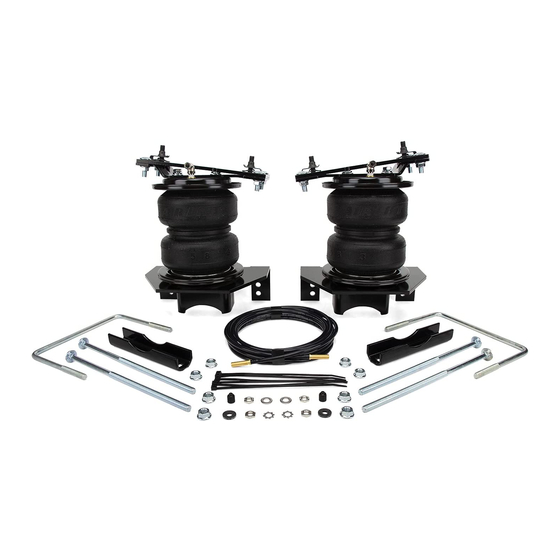
Page 5: Hardware And Tools Lists
21709 Schrader valve with cap & nut ......2 QQ* 21813 AN-to-PTC fitting ..........2 20084 Air line assembly ..........1 Missing or damaged parts? Call Air Lift customer Missing or damaged parts? Call Air Lift customer STOP! service at (800) 248-0892 for a replacement part. -
Page 6: Introduction
LoadLifter 5000 Ultimate kits add an internal jounce bumper and black powder-coated roll plates. LoadLifter 5000 Ultimate Plus kits also have an internal jounce bumper, but add stainless steel roll plates, air lines and air spring mounting hardware. -
Page 7: Installing The Loadlifter 5000 Series System
LoadLifter 5000 Series Installing the LoadLifter 5000 Series System GETTING STARTED 1. Raise and support the vehicle by placing jack stands under the frame rails (or as wide as possible) as shown (Fig. 2). fig. 2 2. Remove the jounce bumpers from under the frame, over the axle. 3. -
Page 8: Side Brace Installation
LoadLifter 5000 Series SIDE BRACE INSTALLATION Fifth-wheel S or BB Driver’s side shown 3/4” Flat washer* (S) bracket (plate) 3/4” Flat washer* or (S) 3/4” Nylon lock nut* or (AA) *3/4” hardware is supplied by the fifth-wheel hitch manufacturer. Use the 3/4”... -
Page 9: Air Spring And Bracket Assembly
LoadLifter 5000 Series AIR SPRING AND BRACKET ASSEMBLY 1. Set a roll plate (G) over the top and bottom of the air spring (H) (Fig. 1). NOTE The radiused (rounded) edge of the roll plate (G) will be toward the air spring so that the air spring is seated inside both roll plates. - Page 10 LoadLifter 5000 Series 5. The lower bracket (B) has two sets of air spring mounting holes. Using the corresponding holes in the lower bracket designated (Figs. 7 & 8), attach the air spring to the brackets using the 3/8”-24 x 3/4” flat-head socket cap screw (FF). Torque mounting screws to no more than 20 lb.-ft.
- Page 11 LoadLifter 5000 Series 7. Set the lower bracket assemblies aside. Insert two 3/8”-16 x 1.25” carriage bolts (P) through the two square holes in both upper brackets (D) (Figs. 10 & 11). Also install one 3/8”-16 x 2.5” carriage bolt (M) through the remaining hole. The head of this carriage bolt will be hidden once the upper bracket is mounted to the air springs.
-
Page 12: Attaching The Assemblies To The Frame
LoadLifter 5000 Series NOTE One of the 3/8”-16 x 1.25” carriage bolts (P) will not be covered by the roll plate and may fall out. If so, retain for use in the “Attaching the Assemblies to the Frame” section later in this installation guide. - Page 13 LoadLifter 5000 Series 4. Raise the axle or lower the frame down so that the thick spacer (F) on the upper bracket is parallel to and contacts the frame (on both sides) (Fig. 16). The spacer must be parallel to the frame with the wide portion facing out toward the wheel.
-
Page 14: Attaching The Lower Bracket
LoadLifter 5000 Series ATTACHING THE LOWER BRACKET NOTE The way the lower bracket is attached depends on the truck model. See Fig. 19 to determine which holes to use for inserting the carriage bolts. 1. Push the lower bracket up against the stock U-bolts so that the legs of the lower bracket are locked into position around the stock U-bolts (Fig. - Page 15 LoadLifter 5000 Series 5. Set the clamp bar (E) over the carriage bolts previously installed that go below the axle and cap with two 3/8” flat washers (Z) and two 3/8”-16 nylon lock nuts (Y) (Figs. 20 & 21). NOTE If the vehicle has a sway bar under the axle and the carriage bolt (Q) interferes, invert the carriage bolt.
-
Page 16: Finishing The Installation
LoadLifter 5000 Series FINISHING THE INSTALLATION 1. Place the modified P-clamp (DD) around the emergency brake cable. Attach the clamp to the lower bracket with the 3/8”-16 x 1” hex cap screw (K), two flat washers (Z) and nylon lock nut (Y). Torque the bolt to 31 lb.-ft. (42Nm) (Fig. 23). A. -
Page 17: Installing The Heat Shield
LoadLifter 5000 Series 1. Cut the air line in half. Make clean, square cuts with a razor blade or hose cutter (Fig. 26). Do not use scissors or wire cutters. Good cut Bad cut fig. 26 Vehicle body 2. Use zip ties to secure the air line to fixed points along the chassis. Do not pinch or kink or bumper the air line. -
Page 18: Finished Installation Photos
LoadLifter 5000 Series Finished Installation Photos 1. The following images show the finished installation of both sides (Figs. 29, 30, 31 & 32). fig. 29 fig. 53 fig. 30 Driver’s (left) side view from the rear. Inside view of the driver’s (left) side. fig. -
Page 19: Before Operating
DO NOT CUT OFF THE AIR LINE OFF AT THE FITTING BECAUSE THIS COULD NICK CAUTION THE BARB AND RENDER THE FITTING USELESS. 3. If the preceding steps have not resolved the problem, call Air Lift customer service at (800) 248-0892. MN-1053... -
Page 20: Installation Checklist
Heat test — Be sure there is sufficient clearance from heat sources, at least 6” (152mm) for air springs and air lines. If a heat shield was included in the kit, install it. If there is no heat shield, but one is required, call Air Lift customer service at (800) 248-0892. -
Page 21: Product Use, Maintenance And Servicing
(18kg) of load (combined on both springs) for each 1 PSI (.07BAR) of pressure. The required air pressure will vary depending on the state of the original suspension. Operating the vehicle below the minimum air spring pressure will void the Air Lift warranty. -
Page 22: Tuning The Air Pressure
LoadLifter 5000 Series TUNING THE AIR PRESSURE Pressure determination comes down to three things — level vehicle, ride comfort and stability. 1 . Level vehicle If the vehicle’s headlights are shining into the trees or the vehicle is leaning to one side, then it is not level (Fig. -
Page 23: Troubleshooting Guide
Q . Will installing air springs increase the weight ratings of a vehicle? No. Adding air springs will not change the weight ratings (GAWR, GCWR and/ or GVWR) of a vehicle. Exceeding the GVWR is dangerous and voids the Air Lift warranty. - Page 24 LoadLifter 5000 Series Notes MN-1053...
- Page 25 LoadLifter 5000 Series Notes MN-1053...
- Page 26 LoadLifter 5000 Series Notes MN-1053...
-
Page 27: Limited Warranty And Return Policy
For additional warranty information contact Air Lift Company customer service. Replacement Part Information If replacement parts are needed, contact the local dealer or call Air Lift customer service at (800) 248-0892. Most parts are immediately available and can be shipped the same day. - Page 28 (517) 322-2144. For calls outside the U.S. or Canada, dial (517) 322-2144. Air Lift Company • 2727 Snow Road • Lansing, MI 48917 or P.O. Box 80167 • Lansing, MI 48908-0167 Printed in the USA JJC-0118...
Need help?
Do you have a question about the LoadLifter 5000 Ultimate and is the answer not in the manual?
Questions and answers